Pages

Thursday, October 30, 2014

Structural Integrity & Materials Selection

Structural integrity
  • the ability of a structure to support a designed load without bending, collapsing, or breaking


Structural failure
  • the loss of structural integrity,


    • created when the material is stressed to its strength limit, thus causing fracture or excessive deformations.
    •  


    Common types of failure:

    1. Fracture:


    Brittle vs. Ductile


    (a) Very ductile, soft metals (e.g. Pb, Au) at room temperature, other metals, polymers, glasses at high temperature.
    (b) Moderately ductile fracture, typical metals
    (c) Brittle fracture, cold metals and ceramics.


    *brittle fracture → rapid run of cracks through  stressed material.  
    *very little plastic deformation
    *No warning → worst type of fracture
    *Amorphous microstructures (glass) produce shiny brittle fracture surfaces


    In crystalline materials:
     transgranular fracture - travels through the grain of the material

      intergranular fracture - crack traveling along the grain boundaries
     
    2. deformation 


    Elastic Deformation:

     - object returns to its original shape

     - Not permanent


    Plastic Deformation:
    - object becomes permanently deformed


    3. Fatigue

    The weakening of a material caused by repeatedly applied loads.


    * microscopic cracks form around small discontinuities at the surface & near grain boundaries. 

    * cracks eventually reaches a critical size, then suddenly propagates through the remainder of the solid.


    Fatigue life depends on:
     
    • Temperature
    • surface finish
    • atomic microstructure
     
     
    Things to avoid:
     Sharp corners & bends - make everything smooth!
     
     
    Example:  90° corner:
    Use the probe to point out where the max stress is:


    Same loading force, comparison of max stress with and without fillet:


    1.411 vs. 0.58 → stress along 90° corner is ~ 2.5 times larger than the stress along the fillet. 


    Find where stress is concentrating on your bridge for various loading conditions, then redesign joints to more homogeneously distribute the load.
     
    ~~~~~~~~~~~~~~~~~~~~~~~~~~~~~~~~~
    Fatigue rules of thumb:
     
  • It can be hard to measure, and get repeatable results on. 
  • Fatigue usually applies to tensile stresses but can also occur under compressive loads.
     
  • ↑stress = shorter life.
  • Damage is cumulative & usually permanent.
  •  

     
    Design Criteria:
     
    Localized failure should not cause immediate or even progressive collapse of the entire structure.


     http://gawker.com/thousands-of-bridges-in-u-s-could-collapse-if-only-sin-509937766


    Test for "critical" spots on your bridge.
    Run a FEA sim where you apply a forces to critical spots (at supports and joints).
     
     
    Modal Analysis
     
    Earthquake? Wind? Vibrating machinery? Vibrating cars & trucks?
     
    Modal Analysis solves for natural vibrational tendencies of a structure in the form of mode shapes and frequencies.


    Try just applying one fixed constraint, and then run the simulation without any other applied forces.
     
    Use the animate tool to watch it vibrate!
     
     
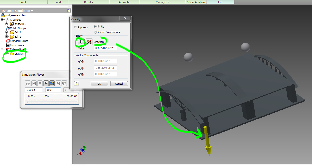
    Display the position of your center of gravity, and notice the influence of the center of gravity on the vibrational patterns in your bridge:
     
    View → Center of Gravity


     Notice how everything vibrates around the center of gravity. 


    Further Reading:
    Mechanical resonance
    Skim through:
    List of bridge failures
    Think about the main causes of bridge failure, and then decide how to modify your bridge to avoid these types of failures.
    Find the mass, volume, center of mass etc. of your part:


    The larger the volume, the more expensive it is to make. 


    What on your bridge is over-designed?  Where can you remove a little bit of material to reduce costs?


    Wednesday, October 29, 2014

    Arch Bridges, Drawing with Equations in Inventor, Stress analysis including gravity


    Rules of thumb for creating arches:For Circular arches - avoid flattened arches
    pg 26:   1/9< rise/span=H/L <1/6 (1/4, 1/3)
         rise/span ~ 1/7.5

    Statics of arches link

    Supporting Forces:

    Consider a simple truss structure


    The load in the compression element increases to infinity as the angle decreases to zero:


    Taller bridges have smaller loads in each member.


    Rule of thumb:  keep H/L ~ 1/7.5


    If H/L does not exceed 1/7.5, what is "H" for your given L?

    example:
    for a bridge using only one arch to span 1000m:
    L = 1,000m (0.62 niles)
    H = (1/7.5)*1000 = 133.333m  (437.445 ft)

    Use Excel or Mathematica to test out your equation! 

    Use the 2D equation to create the arch with Inventor: link

    Start a sketch:

    Read instructions under sketch→line→ equation curve


    Decide on bridge dimensions, then enter equation:

    Offset your line to create a 2D area to extrude:

    Create a bridge!
    Note - I extruded an extra long arch, then cut the road out of the center of it so that it is symmetrical on both sides & in the center.

    You can also import excel points:


    Use the first sheet, A1 = units, A2, B2, C2 = (x,y,z)


    Gravity Stress Analysis:
    The bridge has to support it's own weight as well as the added loads that are applied to it.  Add a gravitational load.


    After you see the FEA results with gravity, create a ball, and open up your bridge in an assembly.

    Constrain the bridge to the ground plane, and the balls to move up and down.


    Once you have all of your constraints in place...

    Simulate a ball falling on your bridge:link
    Open up an assembly, include a ball and your bridge.  Start playing around with the dynamic simulations!

    One good tutorial:
    https://www.youtube.com/watch?v=504xOZcfcbM
    Environment →Dynamic Simulation

    Look at the menu on the left hand side.
    Add and remove joints

     Be sure you are in construction mode, or you cannot change anything!
     Create spatial constraints on your ball to move it from being grounded, to being mobile.

    Either Convert constraints or
    Insert Joint → Spatial →select ball, and then bridge
     Open up all of the options (+) under Grounded, and mobile groups, standing joints, force joints etc. and have a loot around.

    Don't forget to add gravity!
     Right click on your bridge, and ground it if it is not grounded automatically. 

    Output Grapher →open it and have a look around!

    Simulation Settings → decide if you want to automatically create constraints in your dynamic simulation based off of the constraints you created in your assembly...


    Thursday, October 23, 2014

    FEA & Bridges


    FEM  Finite Element Method:

    Breaks large complex geometries into small connected elements in order to analyze things like strength properties.

    Connect nodes with springs:


     Simple linear spring force:


    Simple Stress Strain diagram:


    Materials behave like simple linear springs within their elastic region.


    Some example problems relating Young's Modulus to spring forces:
    https://notendur.hi.is/eme1/skoli/edl_h05/masteringphysics/11/youngsModulus.htm


    Failure Criteria:

    von Mises criterion
    - reasonable estimation of fatigue failure, especially in cases of repeated tensile and tensile-shear loading

     States that failure occurs when the energy of distortion reaches the same energy for yield/failure in uniaxial tension. Mathematically, this is expressed as,


    principle stresses:


    http://demonstrations.wolfram.com/MohrsCircleAndFailureCriterionForPlanarStressStates/


    Review Mechanics of Materials notes:
     http://engr1304.blogspot.com/2014/03/mechanics-of-materials.html


    ~~~~~~~~~~~~~~~~~~~~~~~~~~~~~~~~~~~~~~~~~~~~~~~~~~


    Bridges!


    Create a bridge in Inventor (or import it from CAD into Inventor)
    **Make this as one single part rather than an assembly.  We will do more with constraints on our next project.


     Create a loading blocks where forces can be applied:

    Environment → Stress analysis


    Assign a material to your bridge:


    Apply fixed constraints:

     Apply a load:

    Add mesh

    Play around with the mesh settings, create a tighter mesh in high stress areas.  Update the mesh by right clicking on the red lightning bolt in your files.

    Do the stress analysis!
    Generate a report

    Experiment with the probes
    Investigate different directions of stress and strain


    Civil ENGR & materials design unit

    Bridge Project:

    * Create Bridge (30 points)

    * Apply three different loads (30 points)
    * Re-design Bridge to better support above loads (30 points)
    * Compare 3 different building materials. (10 points)


    Bridge Report and Presentation:
    *Present your bridge to the class (30 points)
    *Create a report detailing the above comparisons (70 points)

    ~~~~~~~~~~~~~~~~~~~~~~~~~~~~
    1. Choose a large bridge to re-create and do a stress analysis on.

     - your recreation will not be exact, but you should use the general form & dimensions of  an existing bridge.
     
    ____/30 points for bridge


    2. Apply 3 different loading conditions 

    (____/ 30 points)

    Loading Condition #1:
    Assume the average person weighs about 150 pounds and occupies ~  2.5 square feet in a crowd...


    Loading Condition #2:


    Approximate wind loads with this simple formula:

    Wind pressure (Psf) = .00256 x V^2
    V = wind speed in mph (use a worst case scenario  of  112 mph → 32 lbs/sq ft)

    Wind Load (Force) = Area * wind pressure * drag coefficient

    Drag coefficient estimates:
    1.2 for long cylinder tubes
    .8 for short cylinders,
    2.0 for long flat plates
    1.4 for shorter flat plates


    http://www.wikihow.com/Calculate-Wind-Load

    http://ascelibrary.org/doi/abs/10.1061/%28ASCE%29BE.1943-5592.0000316?journalCode=jbenf2


    Apply the wind force horizontally to your bridge.


    Loading Condition #3
    Choose the worst-case scenerio road train, get weights/lengths off of the wiki article:

    http://en.wikipedia.org/wiki/Road_train


    3. Redesign part of your bridge to better support each of the above loading conditions.


    4. Show results for 3 different building materials.


    Concrete

    Steel - compare different types
    http://en.wikipedia.org/wiki/I-beam