Gears:
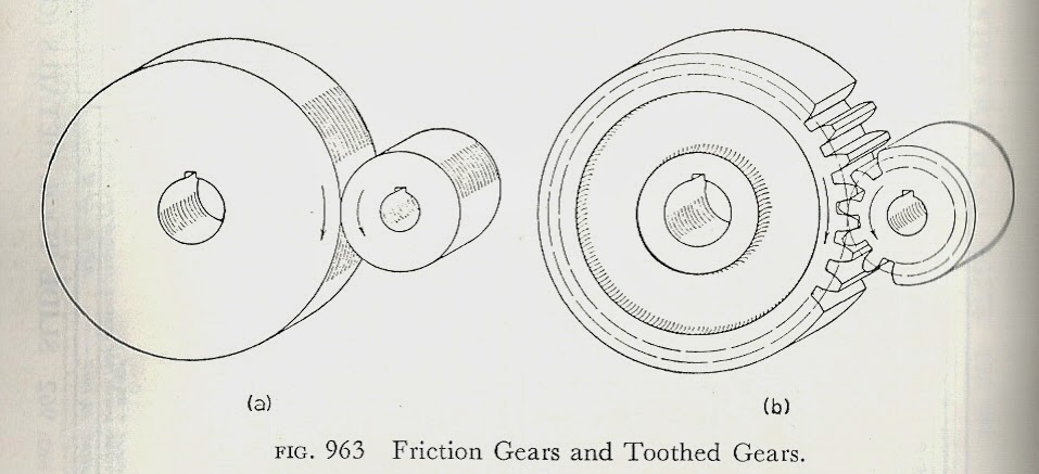


Gears in Inventor
Open an assembly

Click "Create", give it a name, then OK.

Open the Design Tab, and have a look around.

Choose "Spur Gear"
Gear 1 → Component
Gear 2 → No Model
Desired Gear Ratio → Choose 2.00 (instead of 2.4783 - 2.00 is what you need for timing gears)

Calculate:
Check a box near Material Values

Choose the material to make your gear out of:

Assign materials to both Gear1 and Gear2

Set desired Gear Ratio, Preview the gears, run the simulations to see how the teeth come together.

"OK" - creates your first gear:

Choose "Spur Gear" again out of the Design tab
Gear 1 → No Model
Gear 2 → Component
Desired Gear Ratio → Leave what you had it before
Calculate, Ok, Ok,
Place your second gear into your assembly:
Place your second gear into your assembly:

Now, Play around with assembly constraints.
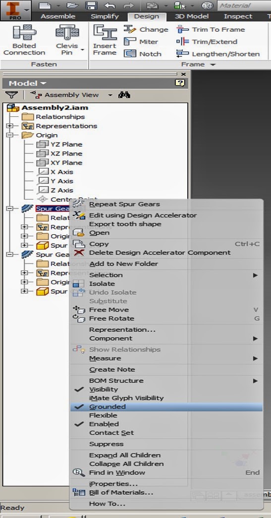
Inventor automatically grounds the first gear you place,
Right click on Spur Gear 1, and deselect "grounded"
After deselecting it, you should be able to grab gear 1, and move it freely around on your screen.
Each part in the assembly has it's own coordinate system, next, we'll constrain both gears to revolve around the world z axis, by snapping their gear z axis to the world z axis.
Click on the (+) to open up all of the coordinate systems.
Constrain Gear#1's z axis to the world origin's Z axis:
Inventor automatically grounds the first gear you place,
Right click on Spur Gear 1, and deselect "grounded"
After deselecting it, you should be able to grab gear 1, and move it freely around on your screen.
Each part in the assembly has it's own coordinate system, next, we'll constrain both gears to revolve around the world z axis, by snapping their gear z axis to the world z axis.
Click on the (+) to open up all of the coordinate systems.
Constrain Gear#1's z axis to the world origin's Z axis:

Test out your z axis constraint - if you choose a front view (with z pointing towards you) you should be able to rotate the gear around z.
Gear 2 should be constrained around an offset z axis, to see how far to offset it, right click on gear 2, then select "Edit using Design Accelerator"
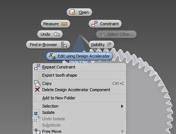
This opens up the spur gear box again, find the center distance (4.00, or 19 inches, or whatever it is) and copy it.

Next, constrain gear 2's z axis around the world axis with a displacement of (4.00 or 19 or whatever the spacing is).
Click on gear 2, then assemble, constrain, gear 2 z axis, origin z axis, change offset to 4.00 (or 19, or whatever it is), apply, OK.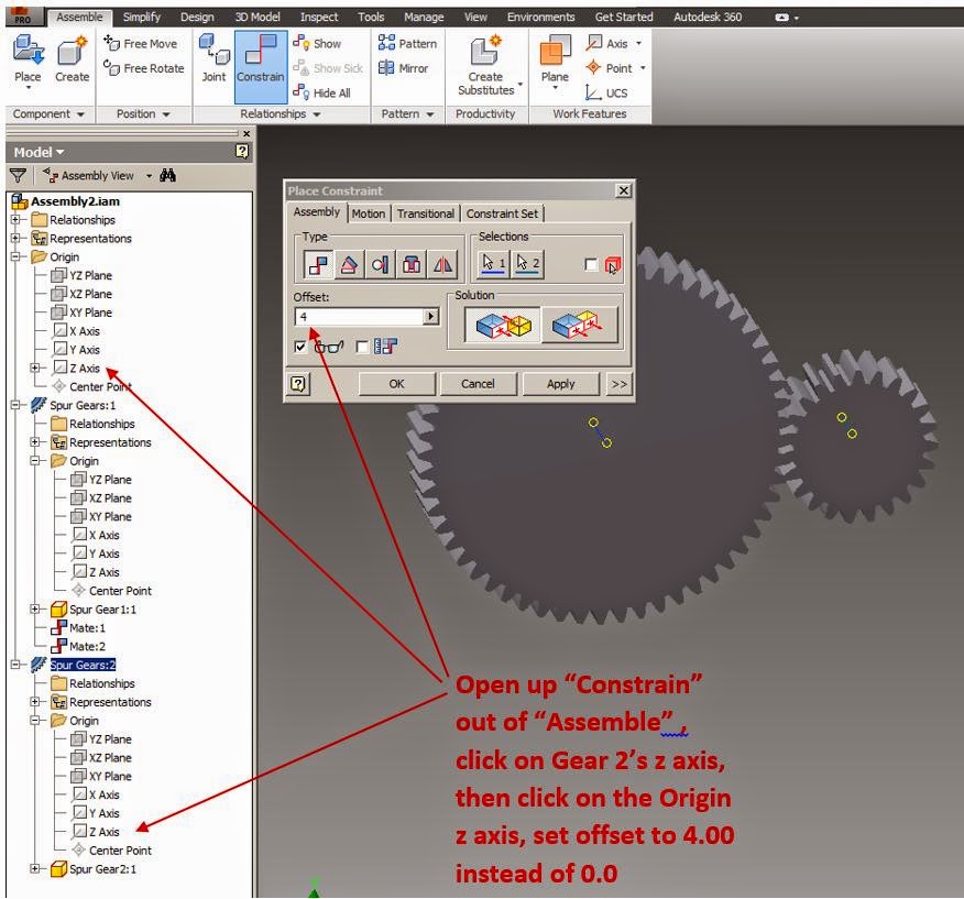
Click on gear 2, then assemble, constrain, gear 2 z axis, origin z axis, change offset to 4.00 (or 19, or whatever it is), apply, OK.
Test out your new constraints - from a Front view, move your gears around, the 2nd gear should rotate freely around the first gear, always maintaining a distance of 4.00.
Look at the constraints that you have generated in the dialog box, this is where you can go back and change them, suppress them, or delete them if you need to.

Next, constrain both gear's z axis to the xz plane:

The only constraint left, is to make the faces flush with one another:

Constrain the faces of both gears to lie along the xy world plane:

Test
out your gear movement, you should be able to rotate each gear about
their axis, and they should be perfectly spaced from one another and in
line with one another.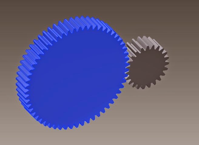
Now, Let's constrain the motion!
Associate → Constrain → Motion
To constrain the motion, we need the gear ratio first, so exist out of constrain motion, and go back to find the gear ratio.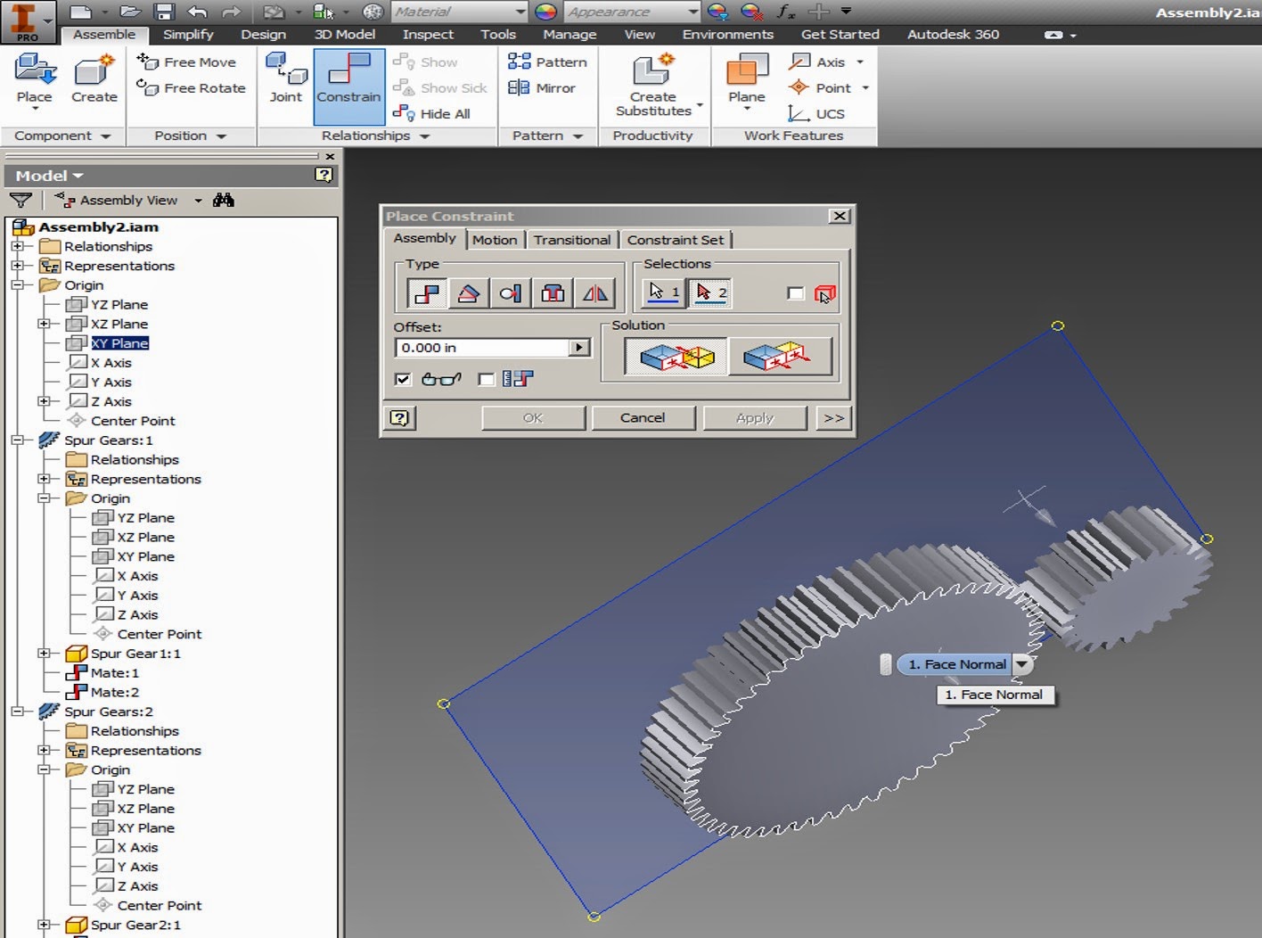
Associate → Constrain → Motion
To constrain the motion, we need the gear ratio first, so exist out of constrain motion, and go back to find the gear ratio.
Right click on a gear, Edit Design Accelerator,
Find your gear ratio, copy it (2.4783ul or 2.00ul) Ctrl + C to copy.
Then go back again to constrain the motion,
Associate → Constrain → Motion
input your gear ratio (2.4783, or 2.00), then select the valley of your large gear first, and then your small gear, choose a reverse solution, Apply, ok. (Note, if you select them in reverse order, your ratio will be 1/2.47 instead of 2.47)
Associate → Constrain → Motion
input your gear ratio (2.4783, or 2.00), then select the valley of your large gear first, and then your small gear, choose a reverse solution, Apply, ok. (Note, if you select them in reverse order, your ratio will be 1/2.47 instead of 2.47)

Check
your gear motion, moving one gear should now move the other gear as
well, but it still isn't perfect! Let's check and fix intersections,
and better align our gears:
Inspect → Analyze Interference → click on gear 1 and gear 2, OK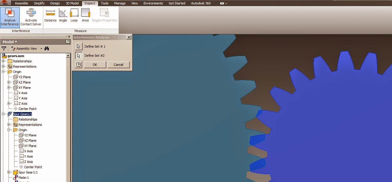
Inspect → Analyze Interference → click on gear 1 and gear 2, OK
Red areas are interference areas.

Suppress your motion constraint by right clicking on it, and selecting suppress. This will allow you to move the gears independently again.

Now move the gears so they line up with one another:
It might be impossible to get them to line up without interference, so let's move the centers away from one another just a little bit.
Just click on the constraint that separates them by 4in (or 19, or whatever the separation is),

Change the separation distance until you get something that just barely works (not too large of a gap!)

Then go back and turn your motion constraint back on (deselect suppress) Hopefully your gears are now turning with one another, without intersections.

Create a simulation:
Start by opening up another constraint,constrain gear 1 with:


If your gears are rotating around the z axis, then link
Gear 1 yz plane → World xz plane

Notice the two blue lines for what planes are being linked.
Right click on the new constraint, choose drive.

We are going to rotate the gear's yz plane about the world xz plane along the z axis for one full revolution.
(Note, make sure you chose the gear with the z axis down the center, and not an offset center)
Press play!

Is anyone up for making timing gears to attach to your engine? Otherwise we'll have to mess with making belts and chains.
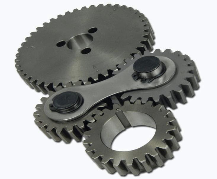
https://www.youtube.com/watch?v=9m1CRJ5ZP_s
Dynamic Simulation:
https://www.youtube.com/watch?v=QDwzDqTG3JU
Dynamic Simulation:
https://www.youtube.com/watch?v=QDwzDqTG3JU


 , where
 = cylinder bore (diameter)
 = piston stroke length
 = clearance volume - the
volume of the combustion chamber (including head gasket). This is the
minimum volume of the space at the end of the compression stroke, i.e.
when the piston reaches top dead center (TDC). Because of the complex
shape of this space, it is usually measured directly rather than
calculated.
= clearance volume - the
volume of the combustion chamber (including head gasket). This is the
minimum volume of the space at the end of the compression stroke, i.e.
when the piston reaches top dead center (TDC). Because of the complex
shape of this space, it is usually measured directly rather than
calculated.


