Pages

Saturday, September 6, 2014

Common CAD Commands


Class Lab - Create a 2D Scribble Page
I'll come around to check you off, just demonstrate that you can use the basic 2D drawing tools outlined below.

You can use tools out of the ribbon, or type commands into the command line.
Some Common CAD Commands:
Remember for all of these CAD commands, WATCH THE COMMAND LINE.  The command line (at the bottom of the screen, where you type commands in) will give you instructions for what information CAD needs to complete the command. [Options are in square brackets], <default – what it will do if you just hit enter without typing anything in>. 

What and How:
First tell CAD "what" you want to do, then tell it "How" you want to do it.

Drawing Commands:
LINE – draws straight lines, keeps drawing lines until you hit “ESC”.  Select line position by clicking on the screen, or entering (x,y) coordinates in the command line. Set linetype by layer.


LTSCALE: Set linetype scale to the drawing scale factor, or half the drawing scale factor.
LTSCALE example: 
change scale factor from .5 to 6, changing the spacing between the dashes.


PSLTSCALE: Makes line type spacing look the same in paper space viewports, regardless of the viewport scale.


  0 =  No special linetype scaling,  1 = Viewport scaling governs linetype scaling

CELTSCALE: Changes the effective line type scale factor for new objects.  
Sets the linetype scaling for new objects relative to the LTSCALE command setting. A line created with CELTSCALE = 2 in a drawing with LTSCALE set to 0.5 would appear the same as a line created with CELTSCALE = 1 in a drawing with LTSCALE = 1.
MSLTSCALE: Visually displays dash-dot linetypes in the model tab based on the annotative scale setting.   0 = Linetypes displayed on the Model tab are not scaled by the annotation scale,
  1 = Linetypes displayed on the Model tab are scaled by the annotation scale

XLINE – Line that extends to infinity in both directions.  In ortho mode, make horizontal or vertical xlines for construction.

Ray: Draws a line that starts at a point, and extends to infinity in one direction.


PLINE – Polyline, connected line segments that can either be straight (line) or curved (arc), etc.  To switch between line types, just watch the command line, and type in a different line type instead of selecting the next point. 
ARC – curved lines

CIRCLE – draws a circle with either defined r, d, or through 2 or 3 points.  Watch command line for [different options on how] to make a circle.
RECTANGLE – draws a rectangle
POLYGON – define how many sides you want it to have.

SPLINE

Modify Commands:

Click on object – grab the blue grips to move & stretch, or type the commands into the command line.  Watch the command line for instructions on what it wants you to do.  You will need to define a base point (reference point that the modify command centers around) for many of these.


MOVE – Moves object, watch the command line for instructions.


ROTATE – select object (enter), type "ROTATE" into command line, select base point (what you want to rotate around), enter, then enter the angle you want to tilt it at, or drag it by hand to tilt it.


EXPLODE – breaks up an object into multiple unattached lines, or a polyline into individual lines and curves.  Explode is helpful if you need to erase one line, or change just part of a shape.


JOIN – connects individual lines into one shape


MIRROR – creates a mirror image of an object


FILLET – creates a rounded corner 

FILLET with r = 0.0 can be used to clean up corners:


Shift-select second line, grabbing the part of the line you do not want cut away.  Now you have a nice corner instead of two intersecting lines!


CHAMFER – chops off a corner with a straight edge

STRETCH, EXTEND, LENGTHEN – elongates an object


EXTEND:
1st - pick boundary edge (what you want to extend to)
2nd - choose object to extend (or f for fence - choose multiple objects to extend


EXTEND to the other side:


TRIM – Cuts off a line at an intersection with another line. 
TRIM (enter)
 - select curved line, enter
- F (fence) enter
- draw a line through the edges you want to remove (horizontal lines on the right of the curved lines), enter


BREAK – take a chunk out of a line


ERASE – erase an object or line

UNDO – undoes your last action

ARRAY – makes multiple copies of an object 
Rectangular Array:


POLAR ARRAY: copies a single object into rows around a central point.


SCALE – makes an object larger or smaller by a defined amount.  First select your object(s), then define your base point (what everything is going to shrink or expand around), then enter a scaling number (0.5 makes it half the size it was, 2 makes it twice as big)

OFFSET – creates a second set of parallel lines around an object – useful for making walls etc.


Text:
TEXT – single line text, the words you type in will not be attached to one another, and can be moved independently.

MTEXT – multiline text, everything you type in will be grouped together, so you can change the size, move it to a new location, etc. together.

Select text, then right click on it, select “properties” to change the size etc.


Dimensioning:
Select dimension, then right click, go to properties to increase text size, etc.
DIMLINEAR – show how long a line is
DIMRADIUS – label the radius of an arc or circle

Thursday, September 4, 2014

AutoCAD Alias Dictionary


  • Scroll down to the yellow section.  
  • Copy this list into excel or word.  
  • When you use a new command, highlight it on your list & write whatever description you need on it.  


Decide on how you want to organize your "command reference" sheet.

Some ideas:
   Group commands according to function. (ie - all 2D drawing commands, all 3D drawing commands, annotation, formatting, etc. etc.)

This will become a good reference / command dictionary for you. Where you will find your "10%".    


;  Program Parameters File For Autodesk AutoCAD 2015
;  External Command and Command Alias Definitions

;  Copyright 2014 Autodesk, Inc.  All rights reserved.
;
;  Use of this software is subject to the terms of the Autodesk license
;  agreement provided at the time of installation or download, or which
;  otherwise accompanies this software in either electronic or hard copy form.

;  Each time you open a new or existing drawing, AutoCAD searches
;  the support path and reads the first acad.pgp file that it finds.

;  -- External Commands --
;  While AutoCAD is running, you can invoke other programs or utilities
;  such Windows system commands, utilities, and applications.
;  You define external commands by specifying a command name to be used
;  from the AutoCAD command prompt and an executable command string
;  that is passed to the operating system.

;  -- Command Aliases --
;  The Command Aliases section of this file provides default settings for
;  AutoCAD command shortcuts.  Note: It is not recommended that  you directly
;  modify this section of the PGP file., as any changes you make to this section of the
;  file will not migrate successfully if you upgrade your AutoCAD to a
;  newer version.  Instead, make changes to the new
;  User Defined Command Aliases
;  section towards the end of this file.

;  -- User Defined Command Aliases --
;  You can abbreviate frequently used AutoCAD commands by defining
;  aliases for them in the User Defined Command Aliases section of acad.pgp.
;  You can create a command alias for any AutoCAD command,
;  device driver command, or external command.

;  Recommendation: back up this file before editing it.  To ensure that
;  any changes you make to PGP settings can successfully be migrated
;  when you upgrade to the next version of AutoCAD, it is suggested that
;  you make any changes to the default settings in the User Defined Command
;  Aliases section at the end of this file.

;  External command format:
;  <Command name>,[<Shell request>],<Bit flag>,[*]<Prompt>,

;  The bits of the bit flag have the following meanings:
;  Bit 1: if set, don't wait for the application to finish
;  Bit 2: if set, run the application minimized
;  Bit 4: if set, run the application "hidden"
;  Bit 8: if set, put the argument string in quotes
;
;  Fill the "bit flag" field with the sum of the desired bits.
;  Bits 2 and 4 are mutually exclusive; if both are specified, only
;  the 2 bit is used. The most useful values are likely to be 0
;  (start the application and wait for it to finish), 1 (start the
;  application and don't wait), 3 (minimize and don't wait), and 5
;  (hide and don't wait). Values of 2 and 4 should normally be avoided,
;  as they make AutoCAD unavailable until the application has completed.
;
;  Bit 8 allows commands like DEL to work properly with filenames that
;  have spaces such as "long filename.dwg".  Note that this will interfere
;  with passing space delimited lists of file names to these same commands.
;  If you prefer multiplefile support to using long file names, turn off
;  the "8" bit in those commands.

;  Examples of external commands for command windows

DEL,       DEL,            8,File to delete: ,
DIR,       DIR,            8,File specification: ,
SH,        ,               1,*OS Command: ,
SHELL,     ,               1,*OS Command: ,
START,     START,          1,*Application to start: ,
TYPE,      TYPE,           8,File to list: ,

; Examples of external commands for Windows
; See also the (STARTAPP) AutoLISP function for an alternative method.

EXPLORER,  START EXPLORER, 1,,
NOTEPAD,   START NOTEPAD,  1,*File to edit: ,
PBRUSH,    START PBRUSH,   1,,


; Command alias format:
;   <Alias>,*<Full command name>

;  The following are guidelines for creating new command aliases.
;  1. An alias should reduce a command by at least two characters.
;      Commands with a control key equivalent, status bar button,
;      or function key do not require a command alias.
;      Examples: Control N, O, P, and S for New, Open, Print, Save.
;  2. Try the first character of the command, then try the first two,
;      then the first three.
;  3. Once an alias is defined, add suffixes for related aliases:
;      Examples: R for Redraw, RA for Redrawall, L for Line, LT for
;      Linetype.
;  4. Use a hyphen to differentiate between command line and dialog
;      box commands.
;      Example: B for Block, -B for -Block.
;
; Exceptions to the rules include AA for Area, T for Mtext, X for Explode.

;  -- Sample aliases for AutoCAD commands --                
;  These examples include most frequently used commands.  NOTE: It is recommended
;  that you not make any changes to this section of the PGP file to ensure the
;  proper migration of your customizations when you upgrade to the next version of
;  AutoCAD.  The aliases listed in this section are repeated in the User Custom
;  Settings section at the end of this file, which can safely be edited while
;  ensuring your changes will successfully migrate.

****************************************

3A,        *3DARRAY
3DMIRROR,  *MIRROR3D
3DNavigate,*3DWALK
3DO,       *3DORBIT
3DP,   *3DPRINT
3DPLOT,    *3DPRINT
3DW,       *3DWALK
3F,        *3DFACE
3M,        *3DMOVE
3P,        *3DPOLY
3R,        *3DROTATE
3S,        *3DSCALE
A,         *ARC
AC,        *BACTION
ADC,       *ADCENTER
AECTOACAD, *-ExportToAutoCAD
AA,        *AREA
AL,        *ALIGN
3AL,       *3DALIGN
AP,        *APPLOAD
APLAY,     *ALLPLAY
AR,        *ARRAY
-AR,       *-ARRAY
ARR,       *ACTRECORD
ARM,       *ACTUSERMESSAGE
-ARM,      *-ACTUSERMESSAGE
ARU,       *ACTUSERINPUT
ARS,       *ACTSTOP
-ARS,       *-ACTSTOP
ATI,       *ATTIPEDIT
ATT,       *ATTDEF
-ATT,      *-ATTDEF
ATE,       *ATTEDIT
-ATE,      *-ATTEDIT
ATTE,      *-ATTEDIT
B,         *BLOCK
-B,        *-BLOCK
BC,        *BCLOSE
BE,        *BEDIT
BH,        *HATCH
BLENDSRF,  *SURFBLEND
BO,        *BOUNDARY
-BO,       *-BOUNDARY
BR,        *BREAK
BS,        *BSAVE
BVS,       *BVSTATE
C,         *CIRCLE
CAM,       *CAMERA
CBAR,      *CONSTRAINTBAR
CH,        *PROPERTIES
-CH,       *CHANGE
CHA,       *CHAMFER
CHK,       *CHECKSTANDARDS
CLI,       *COMMANDLINE
COL,       *COLOR
COLOUR,    *COLOR
CO,        *COPY
CONVTOMESH, *MESHSMOOTH
CP,        *COPY
CPARAM,    *BCPARAMETER
CREASE,    *MESHCREASE
CREATESOLID, *SURFSCULPT
CSETTINGS, *CONSTRAINTSETTINGS
CT,        *CTABLESTYLE
CUBE,      *NAVVCUBE
CURVATUREANALYSIS, *ANALYSISCURVATURE
CYL,       *CYLINDER
D,         *DIMSTYLE
DAL,       *DIMALIGNED
DAN,       *DIMANGULAR
DAR,       *DIMARC
DELETE,    *ERASE
JOG,       *DIMJOGGED
DBA,       *DIMBASELINE
DBC,       *DBCONNECT
DC,        *ADCENTER
DCE,       *DIMCENTER
DCENTER,   *ADCENTER
DCO,       *DIMCONTINUE
DCON,      *DIMCONSTRAINT
DDA,       *DIMDISASSOCIATE
DDEDIT,    *TEXTEDIT
DDI,       *DIMDIAMETER
DDPTYPE,   *PTYPE
DDVPOINT,  *VPOINT
DED,       *DIMEDIT
DELCON,    *DELCONSTRAINT
DI,        *DIST
DIV,       *DIVIDE
DJL,       *DIMJOGLINE
DJO,       *DIMJOGGED
DL,        *DATALINK
DLI,       *DIMLINEAR
DLU,       *DATALINKUPDATE
DO,        *DONUT
DOR,       *DIMORDINATE
DOV,       *DIMOVERRIDE
DR,        *DRAWORDER
DRA,       *DIMRADIUS
DRAFTANGLEANALYSIS, *ANALYSISDRAFTANGLE
DRE,       *DIMREASSOCIATE
DRM,       *DRAWINGRECOVERY
DS,        *DSETTINGS
DST,       *DIMSTYLE
DT,        *TEXT
DV,        *DVIEW
DX,        *DATAEXTRACTION
E,         *ERASE
ED,        *TEXTEDIT
EL,        *ELLIPSE
ER,        *EXTERNALREFERENCES
ESHOT,     *EDITSHOT
EX,        *EXTEND
EXIT,      *QUIT
EXP,       *EXPORT
EXT,       *EXTRUDE
EXTENDSRF, *SURFEXTEND
F,         *FILLET
FI,        *FILTER
FILLETSRF, *SURFFILLET
FREEPOINT, *POINTLIGHT
FSHOT,     *FLATSHOT
G,         *GROUP
-G,        *-GROUP
GCON,      *GEOMCONSTRAINT
GD,        *GRADIENT
GENERATESECTION,  *SECTIONPLANETOBLOCK
GEO,       *GEOGRAPHICLOCATION
GR,        *DDGRIPS
H,         *HATCH
-H,        *-HATCH
HE,        *HATCHEDIT
HB,        *HATCHTOBACK
HI,        *HIDE
I,         *INSERT
-I,        *-INSERT
IAD,       *IMAGEADJUST
IAT,       *IMAGEATTACH
ICL,       *IMAGECLIP
IM,        *IMAGE
-IM,       *-IMAGE
IMP,       *IMPORT
IN,        *INTERSECT
INSERTCONTROLPOINT, *CVADD
INF,       *INTERFERE
IO,        *INSERTOBJ
ISOLATE,   *ISOLATEOBJECTS
QVD,       *QVDRAWING
QVDC,      *QVDRAWINGCLOSE
QVL,       *QVLAYOUT
QVLC,      *QVLAYOUTCLOSE
J,         *JOIN
JOGSECTION,  *SECTIONPLANEJOG
L,         *LINE
LA,        *LAYER
-LA,       *-LAYER
LAS,       *LAYERSTATE
LE,        *QLEADER
LEN,       *LENGTHEN
LESS,      *MESHSMOOTHLESS
LI,        *LIST
LINEWEIGHT, *LWEIGHT
LMAN,      *LAYERSTATE
LO,        *-LAYOUT
LS,        *LIST
LT,        *LINETYPE
-LT,       *-LINETYPE
LTYPE,     *LINETYPE
-LTYPE,    *-LINETYPE
LTS,       *LTSCALE
LW,        *LWEIGHT
M,         *MOVE
MA,        *MATCHPROP
MAT,       *MATBROWSEROPEN
ME,        *MEASURE
MEA,       *MEASUREGEOM
MI,        *MIRROR
ML,        *MLINE
MLA,       *MLEADERALIGN
MLC,       *MLEADERCOLLECT
MLD,       *MLEADER
MLE,       *MLEADEREDIT
MLS,       *MLEADERSTYLE
MO,        *PROPERTIES
MORE,      *MESHSMOOTHMORE
MOTION,    *NAVSMOTION
MOTIONCLS, *NAVSMOTIONCLOSE
MS,        *MSPACE
MSM,       *MARKUP
MT,        *MTEXT
MV,        *MVIEW
NETWORKSRF,*SURFNETWORK
NORTH,     *GEOGRAPHICLOCATION
NORTHDIR,  *GEOGRAPHICLOCATION
NSHOT,     *NEWSHOT
NVIEW,     *NEWVIEW
O,         *OFFSET
OFFSETSRF, *SURFOFFSET
OP,        *OPTIONS
ORBIT,     *3DORBIT
OS,        *OSNAP
-OS,       *-OSNAP
P,         *PAN
-P,        *-PAN
PA,        *PASTESPEC
RAPIDPROTOTYPE, *3DPRINT
PAR,       *PARAMETERS
-PAR,      *-PARAMETERS
PARAM,     *BPARAMETER
PARTIALOPEN, *-PARTIALOPEN
PATCH,     *SURFPATCH
PCATTACH,  *POINTCLOUDATTACH
PE,        *PEDIT
PL,        *PLINE
PO,        *POINT
POFF,      *HIDEPALETTES
POINTON,   *CVSHOW
POINTOFF,  *CVHIDE
POL,       *POLYGON
PON,       *SHOWPALETTES
PR,        *PROPERTIES
PRCLOSE,   *PROPERTIESCLOSE
PROPS,     *PROPERTIES
PRE,       *PREVIEW
PRINT,     *PLOT
PS,        *PSPACE
PSOLID,    *POLYSOLID
PTW,       *PUBLISHTOWEB
PU,        *PURGE
-PU,       *-PURGE
PYR,       *PYRAMID
QC,        *QUICKCALC
QCUI,      *QUICKCUI
QP,        *QUICKPROPERTIES
R,         *REDRAW
RA,        *REDRAWALL
RC,        *RENDERCROP
RE,        *REGEN
REA,       *REGENALL
REBUILD,   *CVREBUILD
REC,       *RECTANG
REFINE,    *MESHREFINE
REG,       *REGION
REMOVECONTROLPOINT, *CVREMOVE
REN,       *RENAME
-REN,      *-RENAME
REV,       *REVOLVE
RO,        *ROTATE
RP,        *RENDERPRESETS
RPR,       *RPREF
RR,        *RENDER
RW,        *RENDERWIN
S,         *STRETCH
SC,        *SCALE
SCR,       *SCRIPT
SE,        *DSETTINGS
SEC,       *SECTION
SET,       *SETVAR
SHA,       *SHADEMODE
SL,        *SLICE
SMOOTH,    *MESHSMOOTH
SN,        *SNAP
SO,        *SOLID
SP,        *SPELL
SPL,       *SPLINE
SPLANE,    *SECTIONPLANE
SPLAY,     *SEQUENCEPLAY
SPLIT,     *MESHSPLIT
SPE,       *SPLINEDIT
SSM,       *SHEETSET
ST,        *STYLE
STA,       *STANDARDS
SU,        *SUBTRACT
T,         *MTEXT
-T,        *-MTEXT
TA,        *TEXTALIGN
TB,        *TABLE
TEDIT,     *TEXTEDIT
TH,        *THICKNESS
TI,        *TILEMODE
TO,        *TOOLBAR
TOL,       *TOLERANCE
TOR,       *TORUS
TP,        *TOOLPALETTES
TR,        *TRIM
TS,        *TABLESTYLE
UC,        *UCSMAN
UN,        *UNITS
-UN,       *-UNITS
UNCREASE,  *MESHUNCREASE
UNHIDE,    *UNISOLATEOBJECTS
UNI,       *UNION
UNISOLATE, *UNISOLATEOBJECTS
V,         *VIEW
VGO,       *VIEWGO
VPLAY,     *VIEWPLAY
-V,        *-VIEW
VP,        *VPOINT
-VP,       *-VPOINT
VS,   *VSCURRENT
VSM,       *VISUALSTYLES
-VSM,      *-VISUALSTYLES
W,         *WBLOCK
-W,        *-WBLOCK
WE,        *WEDGE
WHEEL,     *NAVSWHEEL
X,         *EXPLODE
XA,        *XATTACH
XB,        *XBIND
-XB,       *-XBIND
XC,        *XCLIP
XL,        *XLINE
XR,        *XREF
-XR,       *-XREF
Z,         *ZOOM
ZEBRA,     *ANALYSISZEBRA


**************************************


; The following are alternative aliases and aliases as supplied
;  in AutoCAD Release 13.

AV,        *DSVIEWER
CP,        *COPY
DIMALI,    *DIMALIGNED
DIMANG,    *DIMANGULAR
DIMBASE,   *DIMBASELINE
DIMCONT,   *DIMCONTINUE
DIMDIA,    *DIMDIAMETER
DIMED,     *DIMEDIT
DIMTED,    *DIMTEDIT
DIMLIN,    *DIMLINEAR
DIMORD,    *DIMORDINATE
DIMRAD,    *DIMRADIUS
DIMSTY,    *DIMSTYLE
DIMOVER,   *DIMOVERRIDE
LEAD,      *LEADER
TM,        *TILEMODE

; Aliases for Hyperlink/URL Release 14 compatibility
SAVEURL, *SAVE
OPENURL,   *OPEN
INSERTURL, *INSERT

; Aliases for commands discontinued in AutoCAD 2000:
AAD,        *DBCONNECT
AEX,        *DBCONNECT
ALI,        *DBCONNECT
ASQ,        *DBCONNECT
ARO,        *DBCONNECT
ASE,        *DBCONNECT
DDATTDEF,   *ATTDEF
DDATTEXT,   *ATTEXT
DDCHPROP,   *PROPERTIES
DDCOLOR,    *COLOR
DDLMODES,   *LAYER
DDLTYPE,    *LINETYPE
DDMODIFY,   *PROPERTIES
DDOSNAP,    *OSNAP
DDUCS,      *UCS

; Aliases for commands discontinued in AutoCAD 2004:
ACADBLOCKDIALOG,  *BLOCK
ACADWBLOCKDIALOG, *WBLOCK
ADCENTER,         *ADCENTER
BMAKE,            *BLOCK
BMOD,             *BLOCK
BPOLY,            *BOUNDARY
CONTENT,          *ADCENTER
DDATTE,           *ATTEDIT
DDIM,             *DIMSTYLE
DDINSERT,         *INSERT
DDPLOTSTAMP,      *PLOTSTAMP
DDRMODES,         *DSETTINGS
DDSTYLE,          *STYLE
DDUCS,            *UCSMAN
DDUCSP,           *UCSMAN
DDUNITS,          *UNITS
DDVIEW,           *VIEW
DIMHORIZONTAL,    *DIMLINEAR
DIMROTATED,       *DIMLINEAR
DIMVERTICAL,      *DIMLINEAR
DOUGHNUT,         *DONUT
DTEXT,            *TEXT
DWFOUT,           *PLOT
DXFIN,            *OPEN
DXFOUT,           *SAVEAS
PAINTER,          *MATCHPROP
PREFERENCES,      *OPTIONS
RECTANGLE,        *RECTANG
SHADE,            *SHADEMODE
VIEWPORTS,        *VPORTS
EDWFX,            *EXPORTDWFX
EDWF,             *EXPORTDWF
EPDF,             *EXPORTPDF
-QPUB,            *-EXPORT
; Aliases for commands discontinued in AutoCAD 2007:
RMAT,      *MATBROWSEROPEN
FOG,       *RENDERENVIRONMENT
FINISH,    *MATERIALS
SETUV,     *MATERIALMAP
SHOWMAT,   *LIST
RFILEOPT,  *RENDERPRESETS
RENDSCR,   *RENDERWIN


; Aliases for sysvars discontinued in AutoCAD 2013:
RASTERPREVIEW,      *THUMBSAVE
AUTOCOMPLETE,       *-INPUTSEARCHOPTIONS
AUTOCOMPLETEMODE,   *-INPUTSEARCHOPTIONS
AUTOCOMPLETEDELAY,  *INPUTSEARCHDELAY

; Aliases for commands discontinued in AutoCAD 2014:
3DCONFIG,           *GRAPHICSCONFIG
-3DCONFIG,          *-GRAPHICSCONFIG


;  -- User Defined Command Aliases --
;  Make any changes or additions to the default AutoCAD command aliases in
;  this section to ensure successful migration of these settings when you
;  upgrade to the next version of AutoCAD.  If a command alias appears more
;  than once in this file, items in the User Defined Command Alias take
;  precedence over duplicates that appear earlier in the file.
;  **********----------**********  ; No xlate ; DO NOT REMOVE

ED,      *DDEDIT
PC,      *POINTCLOUD
PCINDEX,      *POINTCLOUDINDEX
TA,      *TABLET
VP,      *DDVPOINT
-VP,      *VPOINT
DASHBOARD,      *RIBBON
DASHBOARDCLOSE,      *RIBBONCLOSE

Intro to AutoCAD!


AutoCAD Intro:

C-A-D 
Computer Aided Drafting 
Computer Aided Design

December 1982 - 1st AutoCAD released, one of the longest-lived programs.

AutoCAD's *.dwg file format standard for most CAD software

Complex and hard to learn?
In 1995 they stopped printing AutoCAD instruction manuals because the documentation package grew to about 12 volumes, and 30 pounds.
Today - a complete set of instruction manuals would take a forklift to move if you printed it.


The good news...
- Few people use more than 10% of the program.
- Most people use the same basic 5%, and a different 5% after that.  It's just a matter of finding your 5%


Getting started:
Free AutoCAD and Inventor download for students:

http://www.autodesk.com/education/free-software/students-university/popular


Open it up:


Welcome Screen:
.


.
Go to the learning resources - 


Bring some ear buds to class so you can watch AutoCAD youtubes, and listen to music during lab.

**everyone has a different background, and will go through this stuff at different speeds.  I'll do basic demos at the beginning of class, but most of your work will be done by using internet resources at your own pace.   


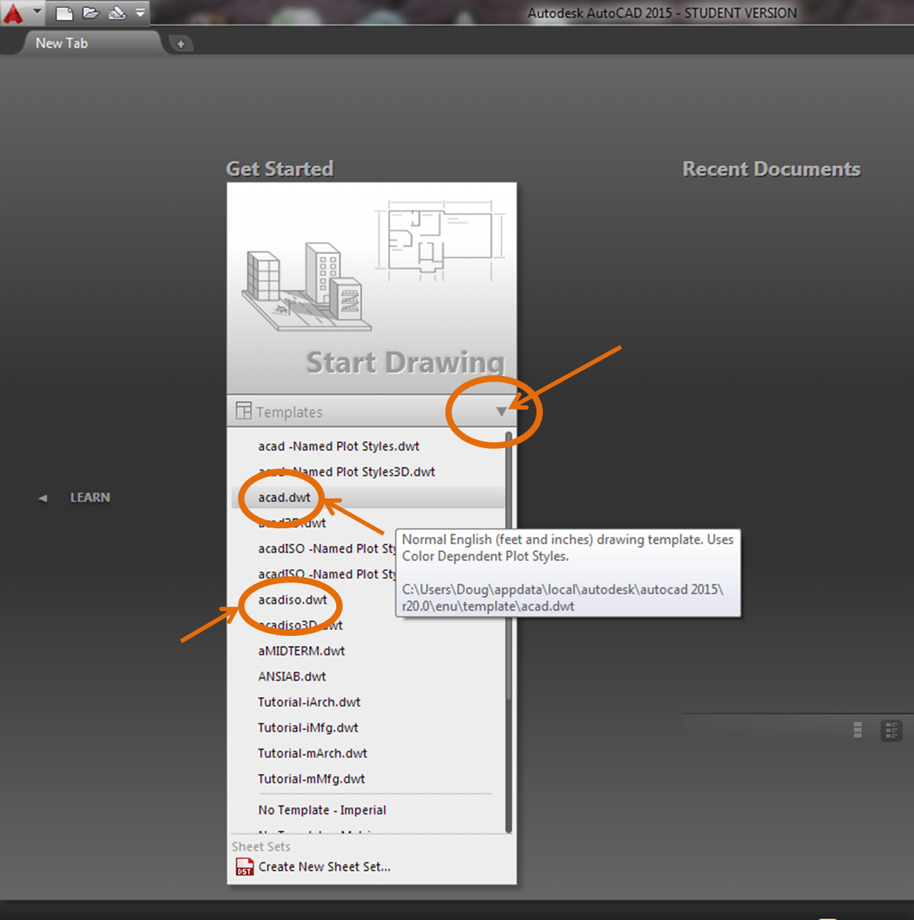
"create" → get back to original welcome screen


→ click on the arrow under "Start Drawing"
→Choose a file format that matches the units you will use.


     acad.dwt    - English template
     acadiso.dwt - metric drawing template

just hold your cursor over a file type, and eventually a window will pop up with a description of the type of file it will create.  

Choose "acad.dwt" to enter the drawing area.


drawing template file  ***.dwt-  specify settings for text, dimensions, linetypes, etc.

drawing file  ***.dwg
   older versions of AutoCAD can't open newer .dwg files

   new versions of CAD can always open older files
   Use the "save as" option to save to older formats if needed


AutoCAD's default opening window:


Hold your cursor over anything, and a description of the icon will pop up.

"What and How"The command line at the bottom of the screen will become your best friend.  When in doubt - just read the command line!!!  The command line is where you tell AutoCAD "What" you want to do, and "How" you want to do it.

Example:
What: polygon  (type "POLYGON" into command line)
How - how many sides do you want your polygon to have?  How large do you want it? Where do you want the center?


Just read the command line, and enter what it asks for.

The basic 42 commands:
basics


Aliases - many CAD commands have aliases - shortcut versions with fewer letters than their full commands, that make it faster to type it into the command line.


L - Line
C - Close
Z A - Zoom All
U - Undo


Create a list of aliases:
 highlight the ones you use most often.

http://e1304.blogspot.com/2014/09/autocad-alias-dictionary.html


The above list of aliases will become a dictionary of commands you can use in the command line.

To start a command, type it's UPPER CASE letter:
command: LINE
alias: L


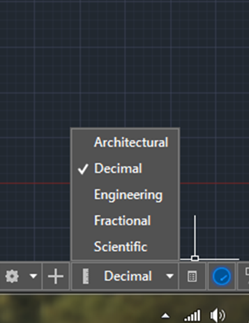
UNITS:  command to set the unit type
- You decide what the length of one unit represents—an inch, a foot, a centimeter, a kilometer, etc.  You should decide what units you need before you start drawing anything.  


- Note: changing the unit format and precision does not affect the internal  precision of your drawing. It affects only how lengths, angles, and coordinates are displayed in the user interface


imperial (i) assume your units are inches, set  unit type to Architectural, use acad.dwt or acadlt.dwt.

metric (m) assume your units are millimeters, leave the unit type set to Decimal, use acadiso.dwt or acadltiso.dwt templates.

If you change the UNITS settings, make sure that you save the drawing as a drawing template file. Otherwise, you will need to change the UNITS settings for each new drawing.


Length Units:
Architectural - units based in feet and inches and use fractions to represent partial inches.  The base unit is one inch.
 

Decimal - units are unitless, that is, they're not based on any particular real-world unit.

Engineering - units are based in feet and inches and use decimals to represent partial inches, for example 12'3.5"

Fractional units, like decimals units, are unitless and show values as fractions rather than decimal numbers: 15 1/2

Scientific units, also unitless and show values as exponents, are used for drawing really tiny or really large. 


Angle Units:
Decimal Degrees: Show angles as decimal numbers, easiest to work with.

Deg/min/sec
 - old style of dividing a degree into minutes and seconds.

Grads and Radians - not widely used in drafting

Surveyor's Units - similar to Deg/Min/Sec but uses quadrants (quarter circles) rather than a whole circle.

Mouse:Left click - select objects, select starting points
Right click in the command line or on anything for options

Wheel:
- Zoom in or out by rolling the wheel.
- Pan a view in any direction by holding the wheel down and then moving your mouse.
- Zoom to the extents of your model by clicking the wheel twice.


~~~~~~~~~~~~~~~~~~~~~~~~~~~~~~~~~~~~~~~~


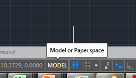
Model vs. Paper space:


Model - Where you create and modify objects that represent things in the real world.  Create your models at full size (1:1 scale).


Paper - Where you create particular views of object for plotting, usually with a title block.  Scale drawing to fit onto the piece of paper you are printing it onto.  Paper space has one or more layouts, each layout has a different arrangement of model space views and different title block information.** Make sure you are in model space when you are drawing!!!


~~~~~~~~~~~~~~~~~~~~~~~~~~~~~~~~~~~~~~~~~~~~~~~~~~~~~~~~~~~~~~~~~~~~~~~

OK - let's start drawing!

Hit "Esc" a couple of times to clear out any previous commands.

Note: You will be hitting Esc over and over again in CAD.  If it is not doing what you want it to, it's probably jammed up with previous commands that have not been turned off.  Hit Esc a few times, and then retry what you were doing.


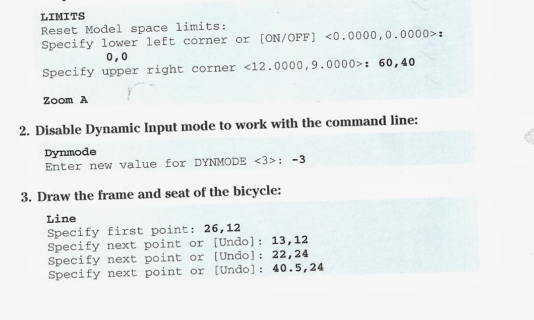
Type the words in bold into the command line at the bottom of your screen.

1. Set up an appropriate size for the drawing:


Now that you are starting to understand this a little, sketch the 3 orthogonal views from pg 57 in CAD.


Use the (x,y) coordinates that you created last week in your excel worksheet to help you with this.  

1. Set your limits to (0,0) - (30,30)
2. Create 4 10 by 10 squares spaced 5 spaces from one another.
3. Create a green layer for construction lines, and a white layer for final lines, and a yellow layer for hidden lines.
4. Sketch in the front view first (lower left hand corner), add construction lines, then fill in the top and side views.

Type in the exact coordinates for all your lines rather than just eyeballing it!


XLINE - creates a line that runs in either direction to infinity - great for making construction lines

DRAWORDER - Allows you to choose which line is on top if lines overlap one another

Set construction lines to be partially transparent within the construction layer.


~~~~~~~~~~~~~~~~~~~~~~~~~~~~~~~~~~~~~~~~~~~~~~~~~~~~~~~~~~~~~~

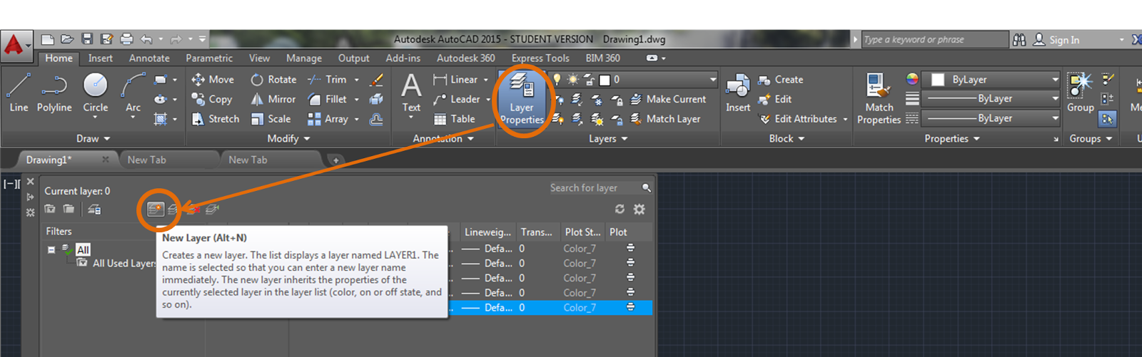
Add layers:- select layer properties


Add new layers:


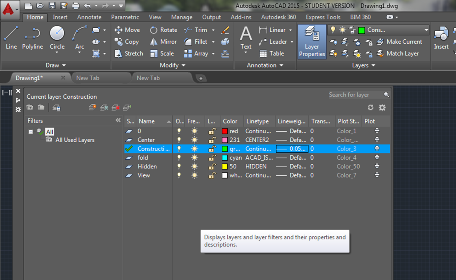
Creates layers for:

  1. View 
  2. Center 
  3. hidden 
  4. construction 
  5. meter line

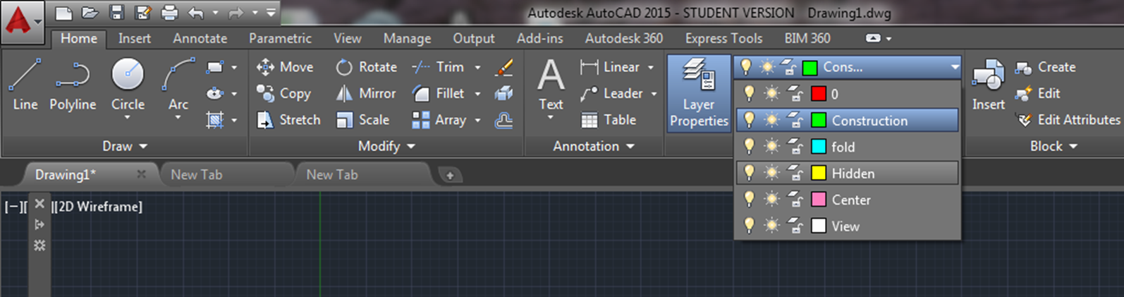
Set line types and line colors for each layer:To change something, just click on it.
You'll need to load the line types, then select one.  


Make the layer you are working on the one on top.


Start by making what you made in excel:
Tip:  Use the up arrow on your keyboard, or enter, to get the previous command you were doing.  (instead of typing in LINE over and over again, just hit enter)


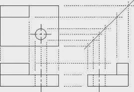
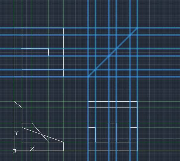
Next, switch layers, and add some green construction "XLINE"'s to show that all of the views line up with one another correctly:

Change the "DRAWORDER" to push the construction lines to the back.


Add a 45° miter line to line up top and right side views.


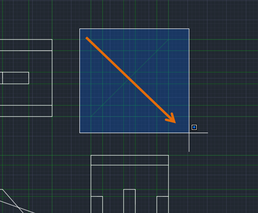
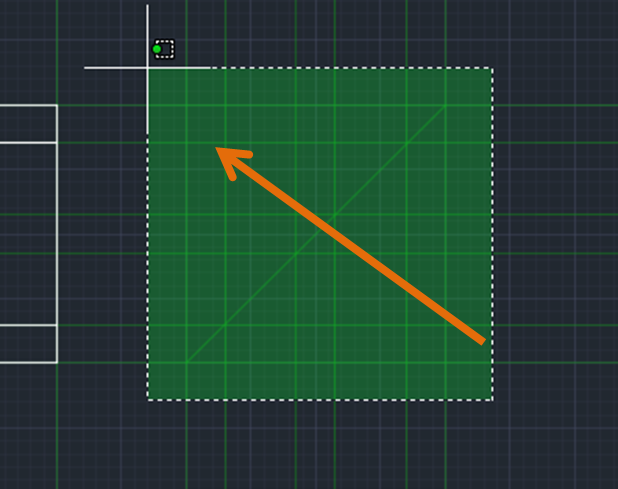
Selection tool tip:
Click left mouse button for a square, 

Hold down left mouse button for a lasso.

If you select something from the left to the right, it will only include what is entirely encompassed within your selection area:


If you select something from the right to the left, it will grab anything that is touching your selection area:


Next - change some lines into hidden lines!


"TRIM" off the sections that should be hidden:
→TRIM

→ <select all> hit enter  (this selects your cutting lines)
note:  whatever is <inside these brackets> will be selected if you just hit enter.

→click on line segments that should be hidden to get rid of them.


Next - get onto your hidden layer:


Use your construction lines to add dashed, yellow, hidden lines in the right spots.  


Are the dashes too small?  Get into your layers box, and change the line type, or type in "LTSCALE"  and entier different values (1?  2? .5?)


Try changing the position of your coordinate system:


UCS  (enter)

Specify origin  (0,15) ← type in the coordinates of where you want the new origin to be

Specify point on x axis → click in the drawing area to orient the x axis horizontally


Specify y axis - click on screen to make the y axis point up.

Need to go back to the original coordinate system?   Just type in UCS (enter) then "W" for world

~~~~~~~~~~~~~~~~~~~~~~~~~~~~~~~


Practice makes perfect! 
Create the rest of your worksheets on CAD:
pg: 61, 65, 75, 77, 67, 69

Save your work and email it to yourself!  We will be using these drawings in the future to add dimensions, title blocks, and format for printing.  
~~~~~~~~~~~~~~~~~~~~~
Done already?  

  • Work on your alias dictionary - look up commands, add definitions, organize your reference sheet.  
~~~~~~~~~~~~~~~~~~~~~~~~~~~~~~~~~~~~~~~~~~~~
More notes on CAD:

Remember to save your work often!
If you do not have a USB drive, just email your files to yourself.


Applications Menu (Big red "A")


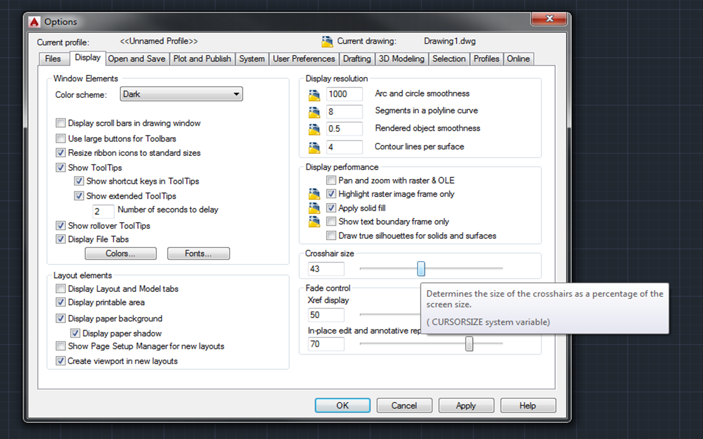
Everything in the work space can be customized by the user.

Example:
Right click on black screen > Display > set user preferences


If someone messes up all the toolbars and settings
Right click on black screen (or type "OPTIONS" into command line)

OPTIONS> Profiles tab> Reset  


Hold your cursor over anything, and a description of the icon will pop up.  


SNAP: 
Restricts cursor movement to specified intervals.


GRID Rectangular pattern of lines or dots that covers the entire XY plane of the user coordinate system (UCS). Using the grid is similar to placing a sheet of grid paper under a drawing. The grid helps you align objects and visualize the distances between them. The grid is not plotted.

If you zoom in or out of your drawing, the grid spacing is adjusted automatically to be more appropriate for the new magnification. This feature is called adaptive grid display.

Set the Grid and snap intervals:


image0.jpg


ORTHO
:
Constrains cursor movement to the horizontal or vertical direction.
POLARIn polar arrays, items are evenly distributed about a center point or axis of rotation.
OSNAP: Object Snap, Snaps new line etc. to an object.

If you enter OSNAP at the Command prompt, the following prompts are displayed.
If you enter -OSNAP at the Command prompt, the following prompts are displayed.
Enter a list of object snap modes
Enter names of object snap modes separated with commas, or enter none or off.

Object Snap Modes

ENDpoint

  CENter

TANgent

MIDpoint

  NODe

NEArest

INTersection

  QUAdrant

PARallel

EXTension 

  INSertion

APParent Intersection 

  PERpendicular 

3DOSNAP3D Object Snap. Set the 3D object snap settings with 3DOSMODE system variable.

Note Because 3D object snaps can slow performance, select only the object snaps you need.

Example options:
OTRACK object snap tracking: Tracks along alignment paths that are based on object snap points.
DUCS  Defined user coordinate system ( UCS ) - change the location of the (0, 0, 0) origin point and the orientation of the XY plane and Z axis. You can locate and orient a UCS anywhere in 3D space, and you can define, save, and recall as many user coordinate systems as you require.
DYN  Dynamic input provides a command interface near the cursor in the drawing area.
LWT:  line weight.  Set line weights by layers.
TPY: Transparency, sets different layers to different transparency levels.
QP: Quick Properties, double click on anything to get it's properties box.
SC: Scale 

Esc - clear command line

Enter or Spacebar - usually repeats previous command, or accepts <default action>.
[command options] in square brackets, type the capital letter "L", "C", to activate command
<default action> inside <>

F1 -  open Help with information about the command in progress.  clicking the "?" also opens help.

F2 - TEXTSCR (or Ctrl F2) - enlarged, scrollable version of the command line

F3 - OSNAP - toggles running object snap mode on and off

F7 - GRID - Turns grid display on and off

F8 - ORTHO toggles ortho mode on and off

F9 - SNAP - Toggles snap mode on and off

F10 - POLAR - Toggles polar mode on and off

F12 -  toggles dynamic input on and off
(F3-F12 are shortcuts for stuff in the status bar)

up and down arrows - scroll through the commands you have used recently.

Ctrl + 0: toggles ribbon off and on to give you a larger working space.
Ctrl +9 turns on the command line - Do NOT turn off the command line.