Pages

Tuesday, October 21, 2014

Creating Layouts for printing in Inventor


Tip: Temporarily disable Auto-constraining by holding down the CTRL key as you draw.

Different file types:
***.ipt - for making parts
***.iam - for assembling parts together
***.idw - for making a drawing / baseviews / page for printing.


From the big red I, select New, then select standard *.idw


Inventor will pull up a default page with a generic title block for  "C" size paper.  We don't want C paper, so right click on your model bar, and delete sheet 1.
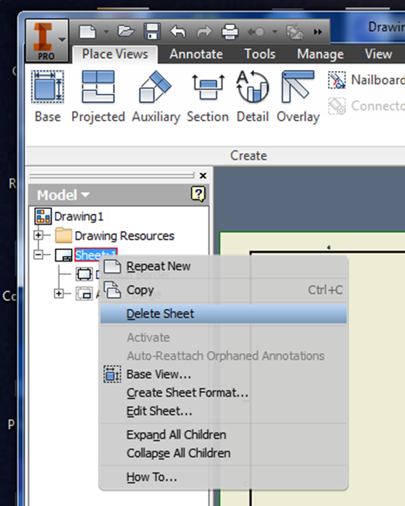

Hit the [+] beside drawing resources, the [+] beside borders, and the [+] beside Title Blocks, select ANSI A titleblock and default border by double clicking on them.


This will give you a standard title block and border.


 Place Views Tab

- Use Base(view) just like in AutoCAD, pull up your file,
  •  change the scale, 
  • choose the orientation of your assembly (bottom, top, etc),
then hit ok, save your assembly, (wait for it to generate the base view), generate additional views, hit Esc when you are done, then move view around to get it where you want it etc.


You can create additional projection, and section views after you hit "Esc." by clicking on the icons in the ribbon.

Projected Views:
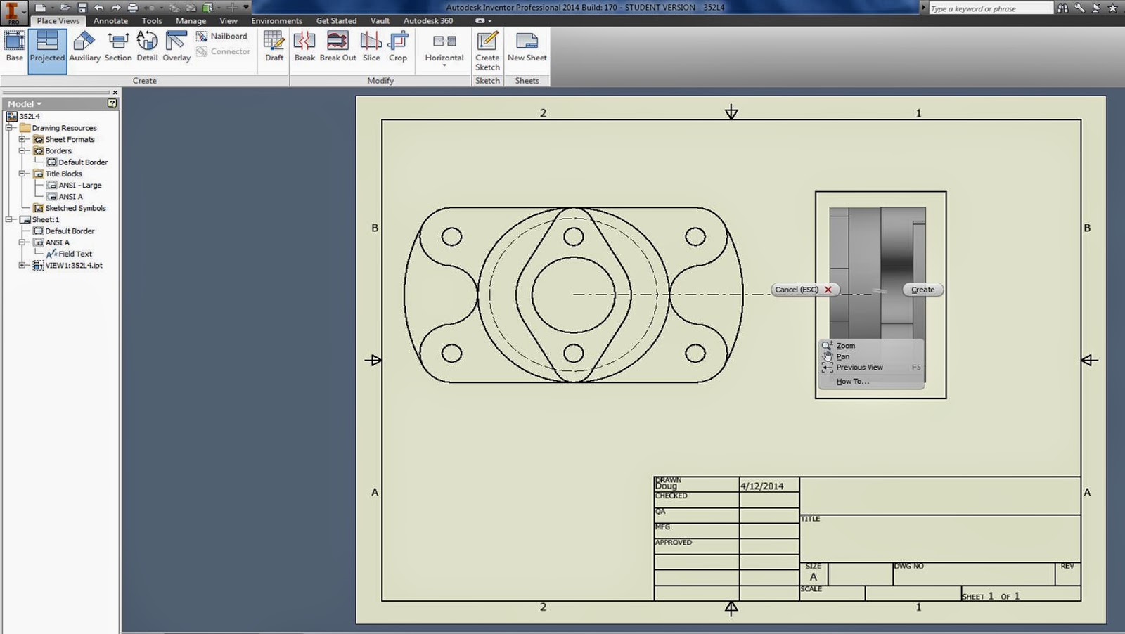
Click on Projected, click on object, pull out a view, Left mouse click to place, then right click to create.


Sectional Views:
Click on "Section"
Draw line where you want to section it.
Right click, continue.


Set your scale, change the Style, etc. then hit ok.


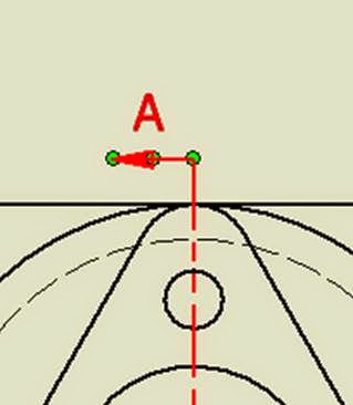
You can click on the green dots to move your A-A sectional line around after it is created.


You can also select a view, and move it around until it is centered.


Annotation TAB:
This is where all of your dimensioning tools are.

Check out the tools in the Annotate Tab:


Skim through the options in the Dimension menu as you are creating dimensions.


Right click on the dimension, (hold down shift to select more than one dimension) Edit dim style, scroll through all of the options.


Changing arrowheads:

Hover over the dimension

When green balls appear, right click,
Choose "Edit 1st / 2nd arrow"


Change Precision:
Double click on dimension, when box comes up just type in the number of sig figs you want.

Title Block:
Click on big I
> iproperties
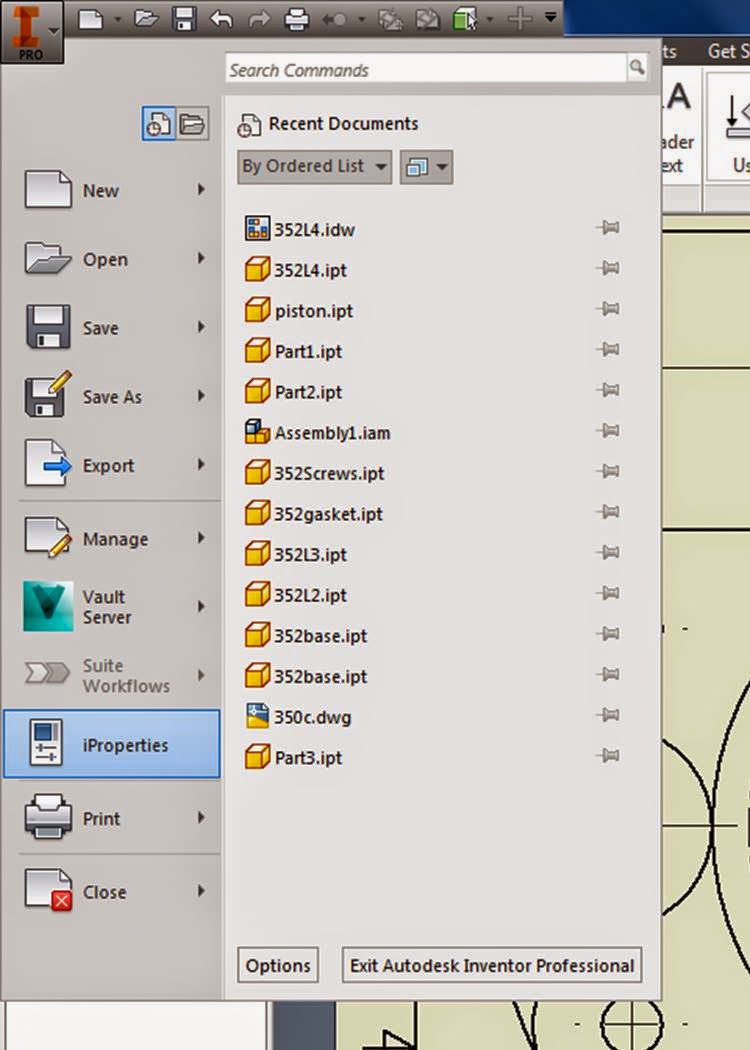
>summary - fill in name etc.
>project - fill in what is needed (you don't have to type something in to each area)
> Apply, close


Working Drawings in Inventor - pg 341

Play around with threaded fasteners:
https://www.youtube.com/watch?v=9d0PA07nZlI


You do not need to use the exact dimensions, just play around with it, create something with the main idea.

Create profile, then use the revolve command.


 For threads, either use the coil command with a cross section:

Create cross section:


 or, try out the thread command.

CAD / Inventor Assembly 
Make a complete set of working drawings for a simple assembly in either Inventor or AutoCAD.  Your set of working drawings should have:


a) An exploded assembly drawing with a parts list, balloons with leader lines.  

b) Individual parts with dimensions and tolerances labeled.


Make a birdhouse similar to the one on pg 343-346
Note: Just "similar", it doesn't have to be exact - change it to use the same size screws through the entire project so you don't have to worry about different hole sizes etc.


(I made everything out of different types of wood etc. so you could more easily see the different parts)


Example hinge:


Pages out of book:


To do this in Inventor:
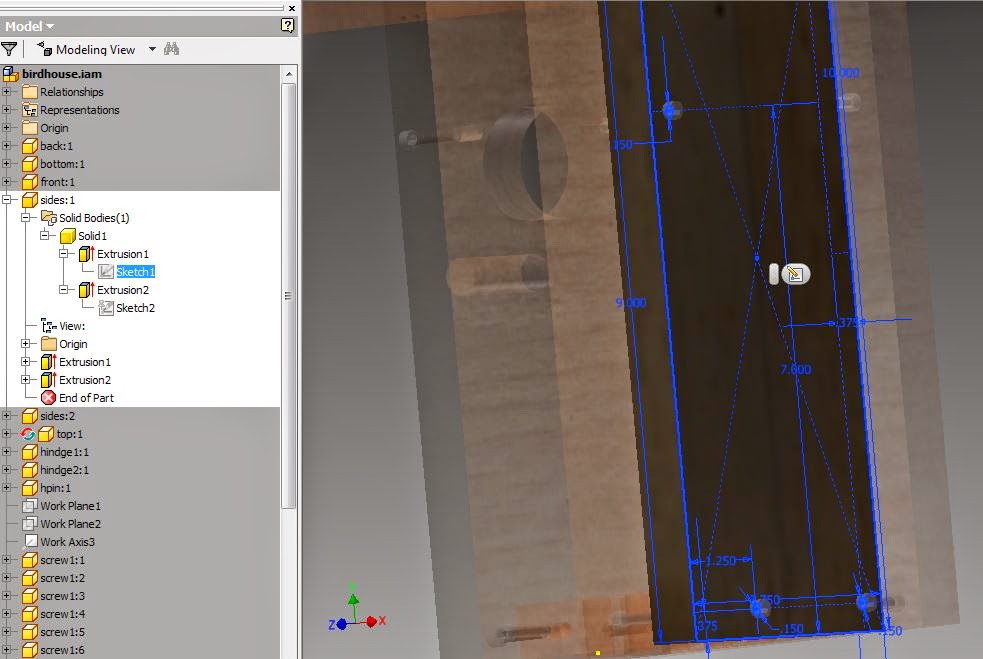
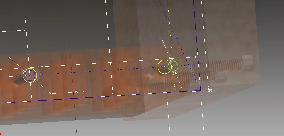
Use "Project Geometry" to line up the holes for the screws.


Put all of your parts together in an assembly, then save and close all of your parts.
Double click on one of the parts in your assembly, then open up the sketch of that part from the modeling window (double click on the sketch you want to edit)


Choose "Project Geometry" from your sketching tools, then click on the holes in other parts, and project them onto the sketching plane for the part you are working on.

Move the hole from your sketches to line up with one another (note - you might have to turn off some of your constraints, or use the move command to do this)

Then "Finish Sketch" and "Return" to get back to where you were.
Save

Making an exploded view in Inventor:

1. Assemble all of your parts so that they are all fully constrained.

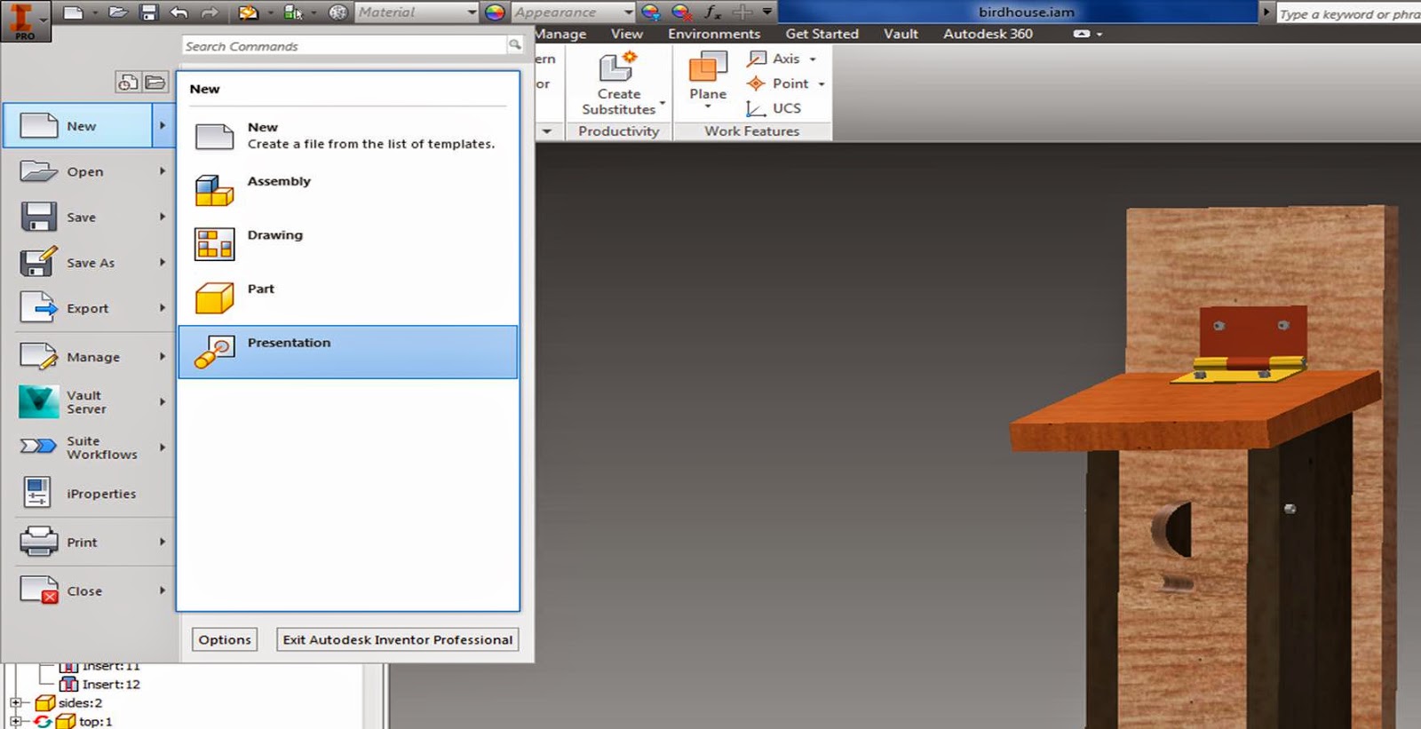
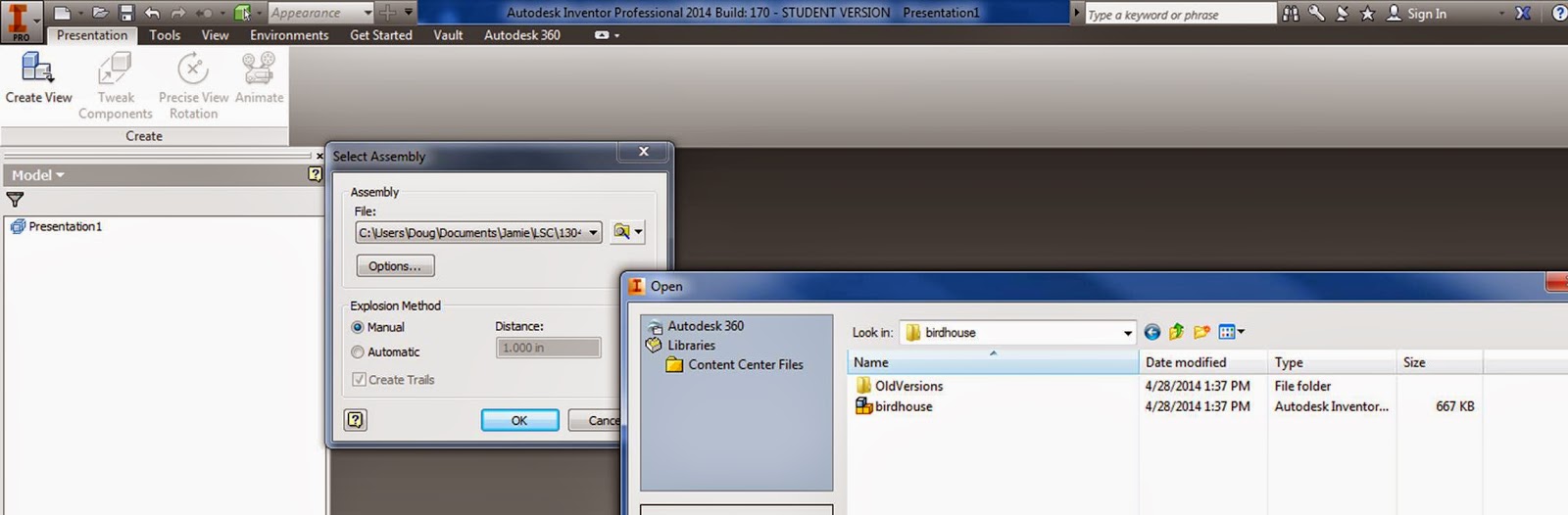
2. New → Presentation


3. Create View → open up your assembly file (click on the little folder on the right hand side of your file) → open

4. You can try to automatically explode it, but this does not always work out so well (especially when you have a lot of parts).... so select "Manual".

5. Tweak Components →Components →choose a part → Direction →click on a face and a direction, grab and pull it away, create a trail →"close" when you are done.

Note: You can select more than one component at a time, so you can move screws together etc. and you can also move in one direction, then click "x , y, or z", and move in another direction before closing.


6. Click "animate" to see your components coming exploding or coming together, then save it.

7.  Create a set of working drawings:
Set up your sheets: - link
Open up multiple sheets:

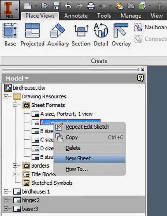
Sheet Format → Choose a size →right click, New Sheet


Create all of the diagrams that you need to,

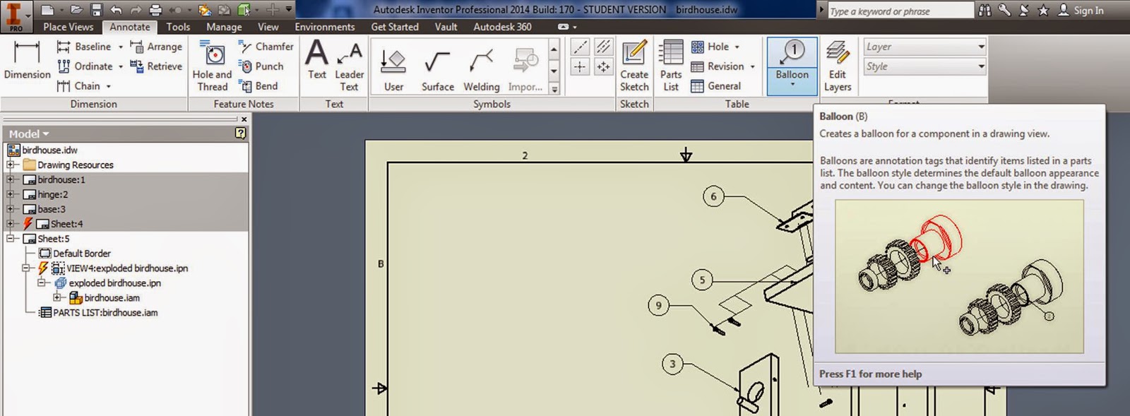
8. Create a Parts list, Balloons, and a PDF etc. for your exploded view:

In your new blank sheet:
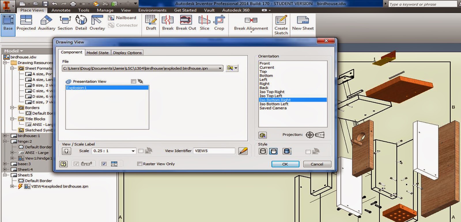
Base view → File (click the magnifying glass, and find your ipn exploded view → change the scale, change the view orientation.


Create a Parts list:
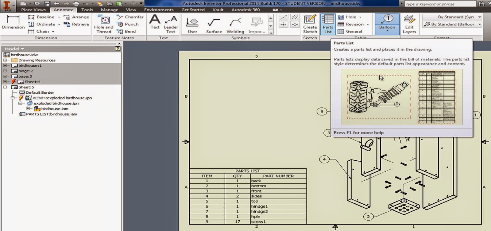
Annotate → Parts List

Click your parts list onto the page.
Right click on it to→ "edit parts list" to change what columns and info it shows:
The upper left hand icon lets you add or remove properties to your parts list:


Then add your bubble part numbers:
It will automatically insert the correct number when you click on a part.


Youtubes going through working drawings in Inventor:
https://www.youtube.com/watch?v=XO2lE9zmhRU

https://www.youtube.com/watch?v=NBQXzL2tOGQ#t=39


Saturday, October 18, 2014

Intro to Inventor

Open up Inventor:


First, create all the individual parts.

Then, assemble them together,
Then create a set of working drawings


Start in 2D, then Extrude into 3D:


Let's start with something simple - similar to the small box on pg 347


Choose a plane start drawing your 2D view on:


It's often best to use the origin... Draw a rectangle centered on the origin


You can dimension the rectangle as you are drawing it, or, change the length of it after you have drawn it with the dimension tool.

Note: In Inventor, you specify the lengths by dimensioning them.  Just double click on any dimension to change the size of your object.

*You can just click on the line to dimension it, you don't have to go corner to corner.


Finish Sketch:


Extrude it just like in AutoCAD!


Note your extrude options:

You can choose the direction you want to go, and if you want to create a solid, or if you want to punch a hole in it.


Note: Each time you create a new sketch, or make a new extrusion, it is saved in the folders on the left of your screen.  You can always go back, reopen your sketch, and change it.


Try out the Fillet command, r = 0.25


Next, let's hollow out the inside of our box - start a new Sketch, and select the top of the box as the sketching plane.


Click on the top of the box
Use the offset command


Use Dimension after you offset to set distance 0.14:


Finish Sketch
Extrude

Push the center out of the box:


Now, add a lip for the lid to slide onto:

Create 2 lines:
Sketch - Offset 0.07 in
Then offset the inner line back out 0.07.


Finish Sketch, push the lip down 0.20


Play around with the drawing tools - decorate the outside of your box!

Use the construction lines, Modify Tools, Constraints, and Patterns!


Explore the View Tab - choose a material, experiment with the different visual styles:


Move a material to the top, then click on the material, and select what part of your object you want to make out of that material.


Save the bottom of your box, and open up a new part to make the top of it.


Make your Lid - decide on a tolerance so that it will slide onto your box easily!


Save your lid, notice that both of your parts can be accessed through the tabs at the bottom of your drawing space:


Now let's put the lid onto your box!
Open up an assembly:


Place both of your parts into your assembly:


Once you have both of your box pieces imported into your assembly, use constraints to snap your lid onto your box:


Notice the different types of constraints:


You can also constrain part of your object to planes in your coordinate system.


The constraints you create show up under your part.

Once you have made a constraint, move your part around to see which ways it can move, and which ways it is stuck.


3D has 6 degrees of freedom - 3 rotational, 3 translational.

You can see which of your degrees of freedom is still available under the view tab:


Constraints are a little tricky to get used to the first time around - changing views (top, front, right) and then moving your object around, helps you see how the constraints are acting.


Click on constraints to see what is paired up with what.

Change the distances the constraints act over - (lower left hand corner)

See if you can constrain the base so that it does not move, and the lid so that it can only move straight up and down.


Once you are done with the box, try out some of the other WS's in chapter 9!