Computer Aided Drafting
Computer Aided Design
December 1982 - 1st AutoCAD released, one of the longest-lived programs.
AutoCAD's *.dwg file format standard for most CAD software
Complex and hard to learn?
In 1995 they stopped printing AutoCAD instruction manuals because the documentation package grew to about 12 volumes, and 30 pounds.
Today - a complete set of instruction manuals would take a forklift to move if you printed it.
The good news...
- Most people use the same basic 5%, and a different 5% after that. It's just a matter of finding your 5%
Getting started:
Free AutoCAD and Inventor download for students:
http://www.autodesk.com/education/free-software/students-university/popular
Open it up:

Welcome Screen:.

.
Go to the learning resources -

Bring some ear buds to class so you can watch AutoCAD youtubes, and listen to music during lab.
**everyone has a different background, and will go through this stuff at different speeds. I'll do basic demos at the beginning of class, but most of your work will be done by using internet resources at your own pace.


"create" → get back to original welcome screen
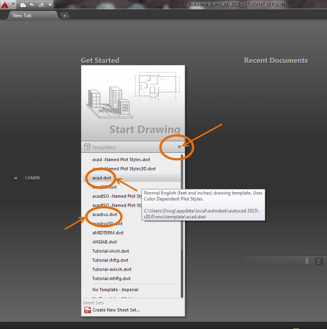
→ click on the arrow under "Start Drawing"
→Choose a file format that matches the units you will use.
acad.dwt - English template
acadiso.dwt - metric drawing template
just hold your cursor over a file type, and eventually a window will pop up with a description of the type of file it will create.
drawing template file ***.dwt- specify settings for text, dimensions, linetypes, etc.
drawing file ***.dwg
older versions of AutoCAD can't open newer .dwg files
new versions of CAD can always open older files
Use the "save as" option to save to older formats if needed

"What and How"The command line at the bottom of the screen will become your best friend. When in doubt - just read the command line!!! The command line is where you tell AutoCAD "What" you want to do, and "How" you want to do it.
Example:
What: polygon (type "POLYGON" into command line)
How - how many sides do you want your polygon to have? How large do you want it? Where do you want the center?


Just read the command line, and enter what it asks for.
The basic 42 commands:
basics

Aliases - many CAD commands have aliases - shortcut versions with fewer letters than their full commands, that make it faster to type it into the command line.
L - Line
C - Close
Z A - Zoom All
U - Undo
Create a list of aliases: highlight the ones you use most often.
http://e1304.blogspot.com/2014/09/autocad-alias-dictionary.html
The above list of aliases will become a dictionary of commands you can use in the command line.
To start a command, type it's UPPER CASE letter:
command: LINE
alias: L
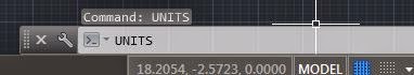
UNITS: command to set the unit type
- You decide what the length of one unit represents—an inch, a foot, a centimeter, a kilometer, etc. You should decide what units you need before you start drawing anything.

- Note: changing the unit format and precision does not affect the internal precision of your drawing. It affects only how lengths, angles, and coordinates are displayed in the user interface
imperial (i) assume your units are inches, set unit type to Architectural, use acad.dwt or acadlt.dwt.
metric (m) assume your units are millimeters, leave the unit type set to Decimal, use acadiso.dwt or acadltiso.dwt templates.
If you change the UNITS settings, make sure that you save the drawing as a drawing template file. Otherwise, you will need to change the UNITS settings for each new drawing.
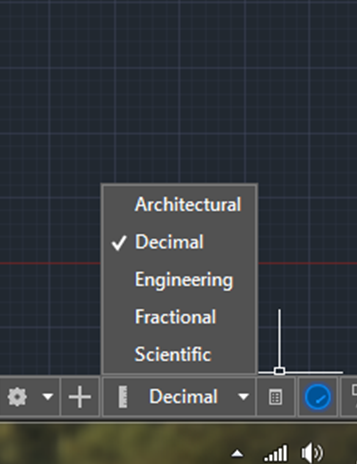
Length Units:
Architectural - units based in feet and inches and use fractions to represent partial inches. The base unit is one inch.
Decimal - units are unitless, that is, they're not based on any particular real-world unit.
Engineering - units are based in feet and inches and use decimals to represent partial inches, for example 12'3.5"
Fractional units, like decimals units, are unitless and show values as fractions rather than decimal numbers: 15 1/2
Scientific units, also unitless and show values as exponents, are used for drawing really tiny or really large.
Angle Units:
Decimal Degrees: Show angles as decimal numbers, easiest to work with.
Deg/min/sec - old style of dividing a degree into minutes and seconds.
Grads and Radians - not widely used in drafting
Surveyor's Units - similar to Deg/Min/Sec but uses quadrants (quarter circles) rather than a whole circle.
Mouse:Left click - select objects, select starting points
Right click in the command line or on anything for options
Wheel:
- Zoom in or out by rolling the wheel.
- Pan a view in any direction by holding the wheel down and then moving your mouse.
- Zoom to the extents of your model by clicking the wheel twice.

~~~~~~~~~~~~~~~~~~~~~~~~~~~~~~~~~~~~~~~~
Model vs. Paper space:
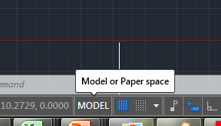
Model - Where you create and modify objects that represent things in the real world. Create your models at full size (1:1 scale).
Paper - Where you create particular views of object for plotting, usually with a title block. Scale drawing to fit onto the piece of paper you are printing it onto. Paper space has one or more layouts, each layout has a different arrangement of model space views and different title block information.** Make sure you are in model space when you are drawing!!!
~~~~~~~~~~~~~~~~~~~~~~~~~~~~~~~~~~~~~~~~~~~~~~~~~~~~~~~~~~~~~~~~~~~~~~~
OK - let's start drawing!
Hit "Esc" a couple of times to clear out any previous commands.
Note: You will be hitting Esc over and over again in CAD. If it is not doing what you want it to, it's probably jammed up with previous commands that have not been turned off. Hit Esc a few times, and then retry what you were doing.
Type the words in bold into the command line at the bottom of your screen.
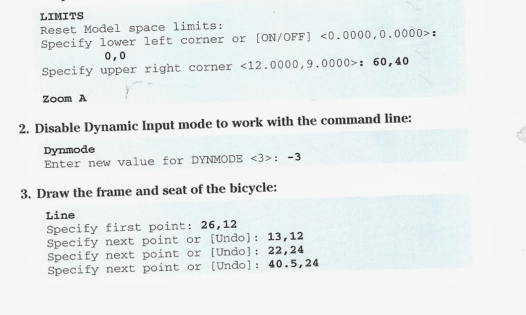
1. Set up an appropriate size for the drawing:

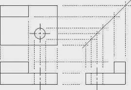
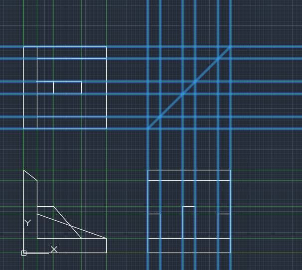
Now that you are starting to understand this a little, sketch the 3 orthogonal views from pg 57 in CAD.
Use the (x,y) coordinates that you created last week in your excel worksheet to help you with this.
1. Set your limits to (0,0) - (30,30)
2. Create 4 10 by 10 squares spaced 5 spaces from one another.
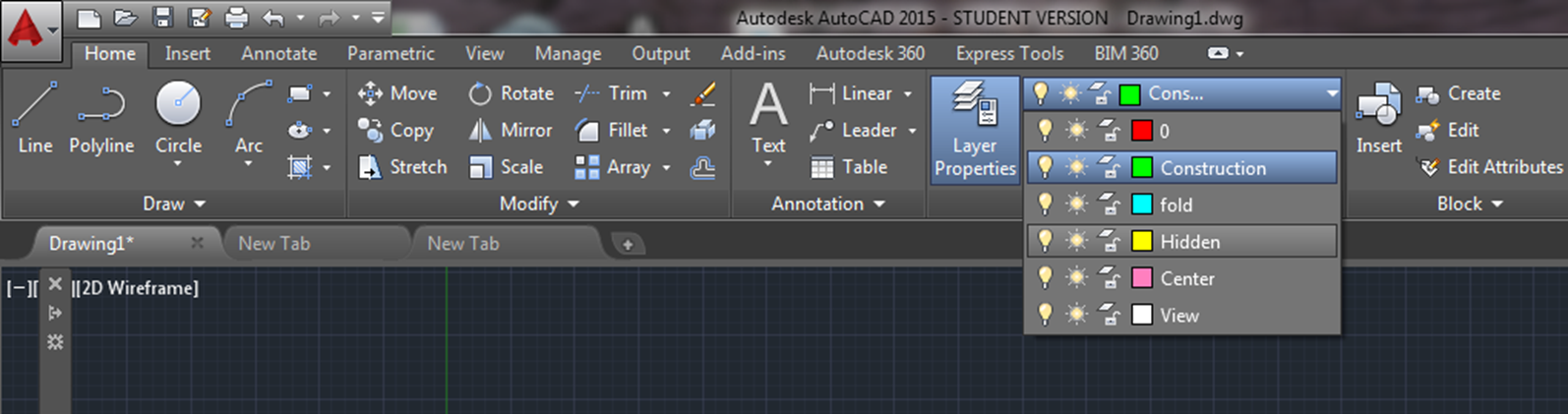
3. Create a green layer for construction lines, and a white layer for final lines, and a yellow layer for hidden lines.
4. Sketch in the front view first (lower left hand corner), add construction lines, then fill in the top and side views.
Type in the exact coordinates for all your lines rather than just eyeballing it!
XLINE - creates a line that runs in either direction to infinity - great for making construction lines
DRAWORDER - Allows you to choose which line is on top if lines overlap one another
Set construction lines to be partially transparent within the construction layer.
~~~~~~~~~~~~~~~~~~~~~~~~~~~~~~~~~~~~~~~~~~~~~~~~~~~~~~~~~~~~~~
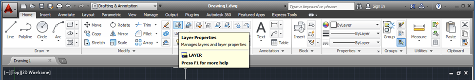
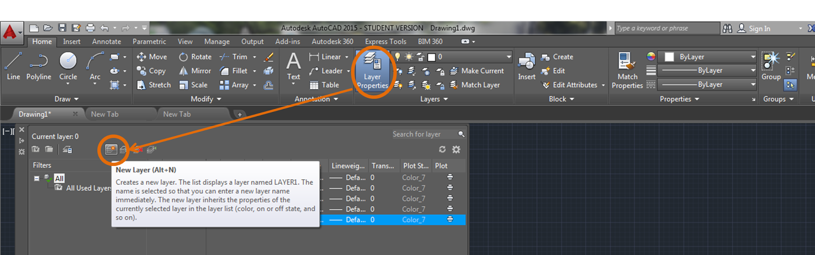
Add layers:- select layer properties
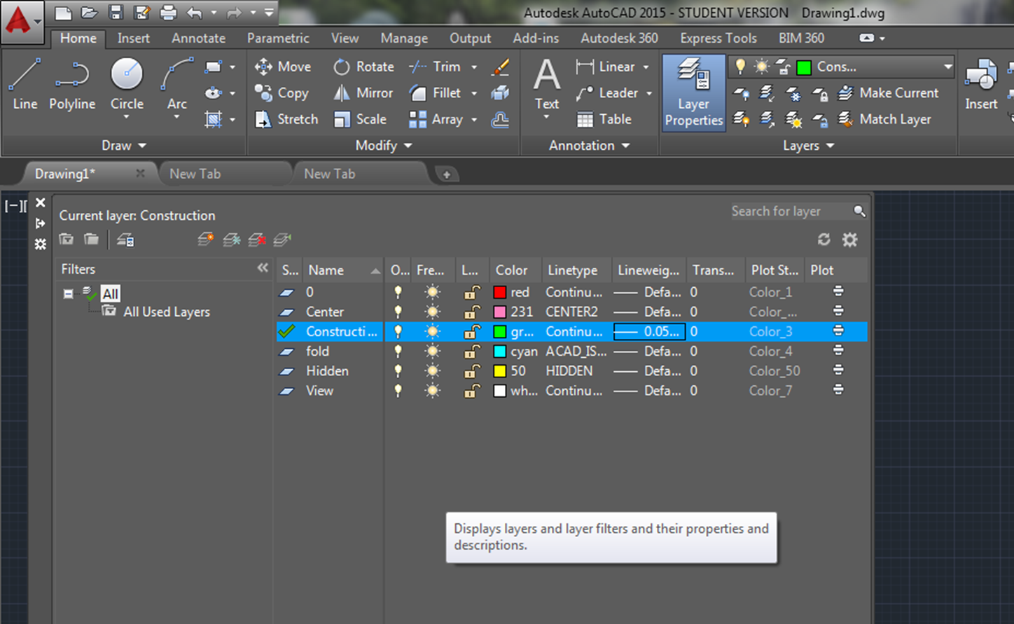
Add new layers:
Creates layers for:
- View
- Center
- hidden
- construction
- meter line
You'll need to load the line types, then select one.
Make the layer you are working on the one on top.
Start by making what you made in excel:
Tip: Use the up arrow on your keyboard, or enter, to get the previous command you were doing. (instead of typing in LINE over and over again, just hit enter)

Next, switch layers, and add some green construction "XLINE"'s to show that all of the views line up with one another correctly:
Change the "DRAWORDER" to push the construction lines to the back.

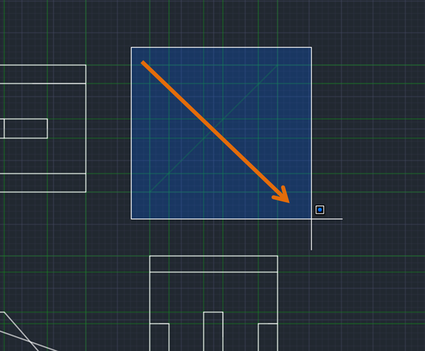
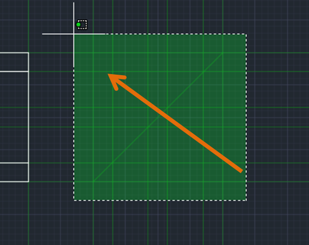
Selection tool tip:
Click left mouse button for a square,
Hold down left mouse button for a lasso.
If you select something from the left to the right, it will only include what is entirely encompassed within your selection area:

If you select something from the right to the left, it will grab anything that is touching your selection area:
Next - change some lines into hidden lines!
"TRIM" off the sections that should be hidden:
→TRIM
→ <select all> hit enter (this selects your cutting lines)
note: whatever is <inside these brackets> will be selected if you just hit enter.
→click on line segments that should be hidden to get rid of them.

Next - get onto your hidden layer:

Use your construction lines to add dashed, yellow, hidden lines in the right spots.

Are the dashes too small? Get into your layers box, and change the line type, or type in "LTSCALE" and entier different values (1? 2? .5?)

Try changing the position of your coordinate system:


UCS (enter)
Specify origin (0,15) ← type in the coordinates of where you want the new origin to be
Specify point on x axis → click in the drawing area to orient the x axis horizontally
Specify y axis - click on screen to make the y axis point up.
Need to go back to the original coordinate system? Just type in UCS (enter) then "W" for world
~~~~~~~~~~~~~~~~~~~~~~~~~~~~~~~
Practice makes perfect!
Create the rest of your worksheets on CAD:
pg: 61, 65, 75, 77, 67, 69
Save your work and email it to yourself! We will be using these drawings in the future to add dimensions, title blocks, and format for printing.
~~~~~~~~~~~~~~~~~~~~~
Done already?
- Work on your alias dictionary - look up commands, add definitions, organize your reference sheet.
More notes on CAD:
Remember to save your work often!
If you do not have a USB drive, just email your files to yourself.
Remember to save your work often!
If you do not have a USB drive, just email your files to yourself.

Applications Menu (Big red "A")

Everything in the work space can be customized by the user.
Example:
Right click on black screen > Display > set user preferences
If someone messes up all the toolbars and settings
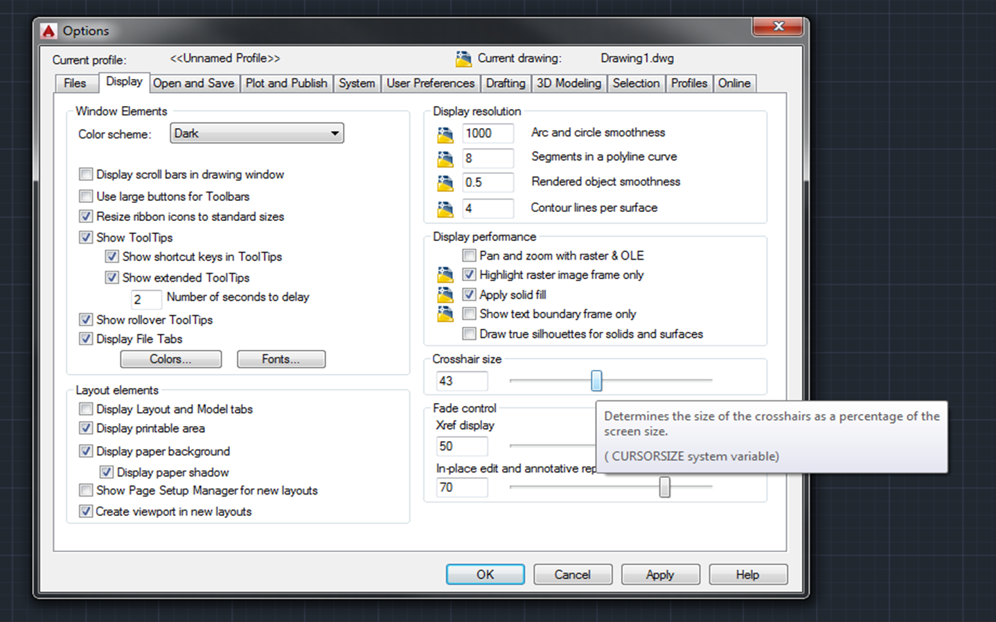
Right click on black screen (or type "OPTIONS" into command line)
Example:
Right click on black screen > Display > set user preferences
If someone messes up all the toolbars and settings
Right click on black screen (or type "OPTIONS" into command line)
OPTIONS> Profiles tab> Reset

Hold your cursor over anything, and a description of the icon will pop up.


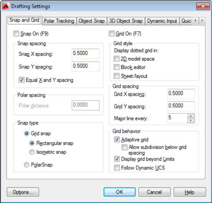
Restricts cursor movement to specified intervals.

GRID Rectangular pattern of lines or dots that covers the entire XY plane of the user coordinate system (UCS). Using the grid is similar to placing a sheet of grid paper under a drawing. The grid helps you align objects and visualize the distances between them. The grid is not plotted.
If you zoom in or out of your drawing, the grid spacing is adjusted automatically to be more appropriate for the new magnification. This feature is called adaptive grid display.
Set the Grid and snap intervals:
ORTHO:
POLARIn polar arrays, items are evenly distributed about a center point or axis of rotation.
OSNAP: Object Snap, Snaps new line etc. to an object.
If you enter -OSNAP at the Command prompt, the following prompts are displayed.
ENDpoint
|
CENter
|
TANgent
|
MIDpoint
|
NODe
|
NEArest
|
INTersection
|
QUAdrant
|
PARallel
|
EXTension
|
INSertion
| |
APParent Intersection
|
PERpendicular
|
3DOSNAP3D Object Snap. Set the 3D object snap settings with 3DOSMODE system variable.
Example options:
OTRACK object snap tracking: Tracks along alignment paths that are based on object snap points.
DUCS Defined user coordinate system ( UCS ) - change the location of the (0, 0, 0) origin point and the orientation of the XY plane and Z axis. You can locate and orient a UCS anywhere in 3D space, and you can define, save, and recall as many user coordinate systems as you require.
DYN Dynamic input provides a command interface near the cursor in the drawing area.
LWT: line weight. Set line weights by layers.
TPY: Transparency, sets different layers to different transparency levels.
QP: Quick Properties, double click on anything to get it's properties box.
SC: Scale
Esc - clear command line
Enter or Spacebar - usually repeats previous command, or accepts <default action>.
[command options] in square brackets, type the capital letter "L", "C", to activate command
<default action> inside <>
F1 - open Help with information about the command in progress. clicking the "?" also opens help.
F2 - TEXTSCR (or Ctrl F2) - enlarged, scrollable version of the command line
F3 - OSNAP - toggles running object snap mode on and off
F7 - GRID - Turns grid display on and off
F8 - ORTHO toggles ortho mode on and off
F9 - SNAP - Toggles snap mode on and off
F10 - POLAR - Toggles polar mode on and off
F12 - toggles dynamic input on and off
(F3-F12 are shortcuts for stuff in the status bar)
up and down arrows - scroll through the commands you have used recently.
Ctrl + 0: toggles ribbon off and on to give you a larger working space.
No comments:
Post a Comment