
Rules of thumb for creating arches:For Circular arches - avoid flattened arches
pg 26: 1/9< rise/span=H/L <1/6 (1/4, 1/3)
rise/span ~ 1/7.5
Statics of arches link
Statics of arches link
Supporting Forces:
Consider a simple truss structure

The load in the compression element increases to infinity as the angle decreases to zero:

Taller bridges have smaller loads in each member.

Rule of thumb: keep H/L ~ 1/7.5

If H/L does not exceed 1/7.5, what is "H" for your given L?
example:
for a bridge using only one arch to span 1000m:
L = 1,000m (0.62 niles)
example:
for a bridge using only one arch to span 1000m:
L = 1,000m (0.62 niles)
H = (1/7.5)*1000 = 133.333m (437.445 ft)
Use Excel or Mathematica to test out your equation!
Use the 2D equation to create the arch with Inventor: link
Start a sketch:

Read instructions under sketch→line→ equation curve


Decide on bridge dimensions, then enter equation:

Offset your line to create a 2D area to extrude:

Create a bridge!
Note - I extruded an extra long arch, then cut the road out of the center of it so that it is symmetrical on both sides & in the center.

You can also import excel points:


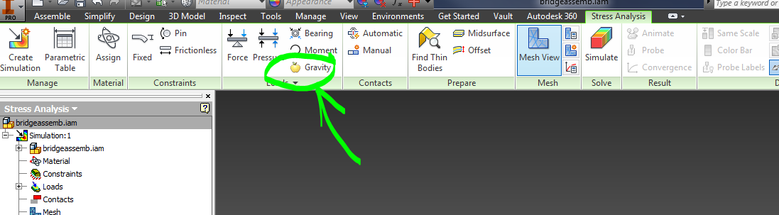
Gravity Stress Analysis:
The bridge has to support it's own weight as well as the added loads that are applied to it. Add a gravitational load.
After you see the FEA results with gravity, create a ball, and open up your bridge in an assembly.
Constrain the bridge to the ground plane, and the balls to move up and down.


Once you have all of your constraints in place...
Simulate a ball falling on your bridge:link
Open up an assembly, include a ball and your bridge. Start playing around with the dynamic simulations!
One good tutorial:
https://www.youtube.com/watch?v=504xOZcfcbM
One good tutorial:
https://www.youtube.com/watch?v=504xOZcfcbM
Environment →Dynamic Simulation

Look at the menu on the left hand side.
Add and remove joints

Be sure you are in construction mode, or you cannot change anything!

Create spatial constraints on your ball to move it from being grounded, to being mobile.
Either Convert constraints or
Either Convert constraints or
Insert Joint → Spatial →select ball, and then bridge

Open up all of the options (+) under Grounded, and mobile groups, standing joints, force joints etc. and have a loot around.
Don't forget to add gravity!
Don't forget to add gravity!
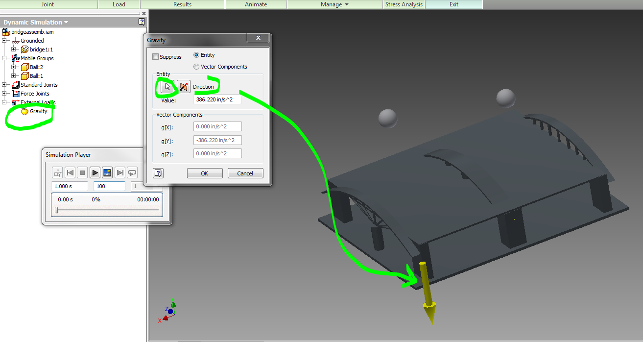
Right click on your bridge, and ground it if it is not grounded automatically.

Output Grapher →open it and have a look around!
Simulation Settings → decide if you want to automatically create constraints in your dynamic simulation based off of the constraints you created in your assembly...
No comments:
Post a Comment