3 major components of working drawings:
1. Drawing that shows how parts are assembled
1. Drawing that shows how parts are assembled
2.Orthographic views of all the parts
3. Notes for all the standard parts
Assembly Drawings:
First(or last) page in a set of working drawings
Used to show how all the parts fit together.
Pictorial format - isometric, or perspective
Oriented to best show geometry of parts
Route lines - lines connecting components to one another
No hidden lines, centerlines, or dimensions
Part number balloon - circle with number that identifies part
Keep Part numbers consistent through drawing
Table with parts list - corresponding to part numbers.
Typical parts list:
Part number
Part name
Material Used
Required Quantity
Collapsed (parts assembled together)
Exploded (the assembly pulled apart)
pg 350:

In AutoCAD: To insert a table, just type "TABLE", then fill in the cells like you would in excel.
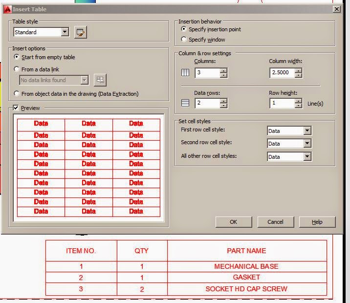
For the Balloons with leader lines, type in "TP" for Tool Pallet.
Annotation - tag.
Check out all of the other tools in the tool pallet while you are there!
To rescale the size, or change anything, just select it, right click, and go to the properties box.

Detail Drawings
Orthogonal views
Dimensions for manufacturing
Part name tag
Part number balloon tag
Just use your normal dimensioning tools, then go back and double click on the dim to add more info.
%%c makes the diameter symbol


Vendor items
no orthographic views, just need a note with part info
Construction notes if needed
Outline how to assemble parts, what types of glues and materials to use, etc.
Choice:
Create working drawing WS's in AutoCAD - then export into inventor - or - just create them in Inventor.
** If the computers are crashing when Inventor is up, we might be forced to use CAD for a little while longer. Sorry!!!
Read about Inventor on Wiki: http://en.wikipedia.org/wiki/Autodesk_Inventor
File types
1. *.ipt for individual parts
2. *.iam for assembly
3. *idw for drafting docs
4. *.ipn – for exploded renderings of assemblies & presentations (not in LT version)
I'll walk you through creating some of pg 350 (that we just did in CAD) in Inventor so you can see how it works. I think you'll find that learning Inventor will be very easy after learning CAD as they share many of the same tools.
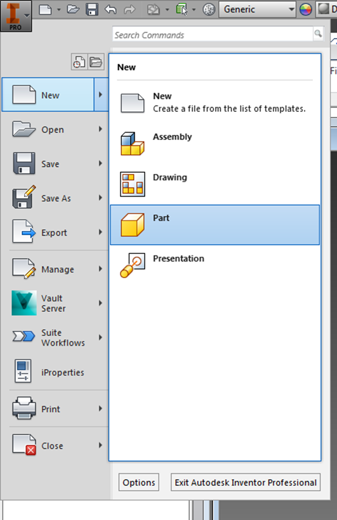
Start by creating a single part:
I - New - Part
Click 2D sketch (upper left hand corner), Chose a plane to sketch on -
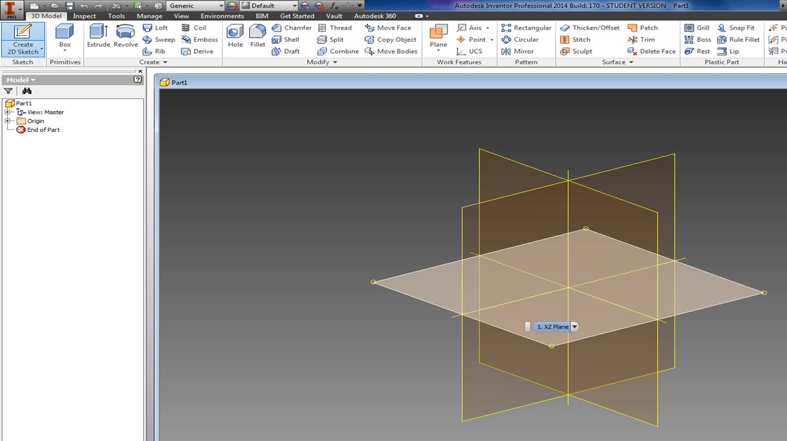
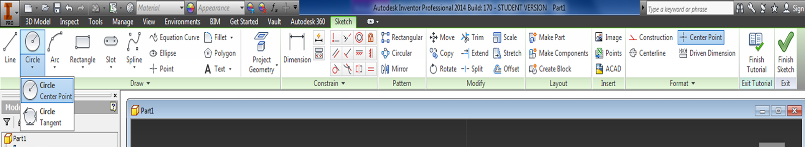
Notice that the drawing tools (Sketch) in Inventor are similar to what they are in AutoCAD.
Your mouse works similarly in Inventor too:
Use scroll wheel to zoom in and out, etc.
Use the view cube (just like in CAD) rotate "TOP" to be right side up instead of upside down. (Inventor starts upside down for some reason)
Differences from CAD:
Instead of drawing everything in the right spot to begin with, use constrain.
Draw two randomly oriented lines, and explore the constrain tools:
Note:
- New line segments will continue to be drawn until you press Enter or Esc.
- Enter - keeps the previous command open, so if you click again, you will start a new line segment.
- Esc. - ends line command.
 Once you have drawn your two lines, use the // parallel icon in the
constrain tab to change the lines so that they are parallel to one
another:
Once you have drawn your two lines, use the // parallel icon in the
constrain tab to change the lines so that they are parallel to one
another:Click the // icon in the Constrain tab, then click on both of your lines:
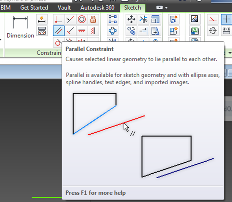
This moves your lines so that they are now parallel to one another.
Right click on one of your lines, select "Show constraints"
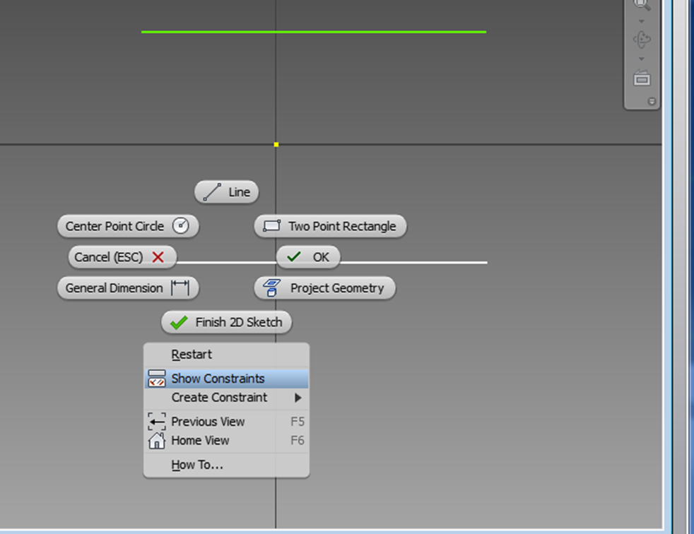
Or use the Show Constraints icon:
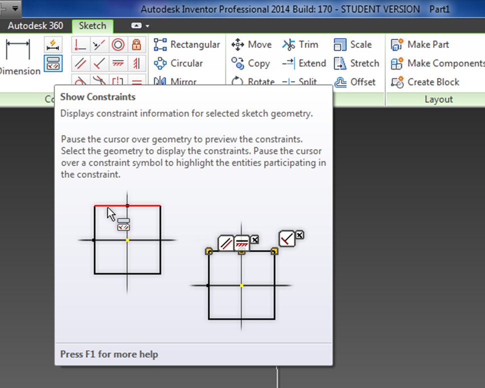
Click on your lines - The symbols shown next to your lines indicate their constraints.

Note: To delete a constraint, Esc. out of everything you are doing, then right click on the constraint, and select "delete". (Clicking on the [x] does not delete it, it just removes the label.)

Highlight a line & click on it to move it around (or use the Move command in the Modify tab, select a base point). Notice that your constrained lines will move up and down, but will remain parallel to one another.

Next, just to play around, connect the ends of your lines with an arc:
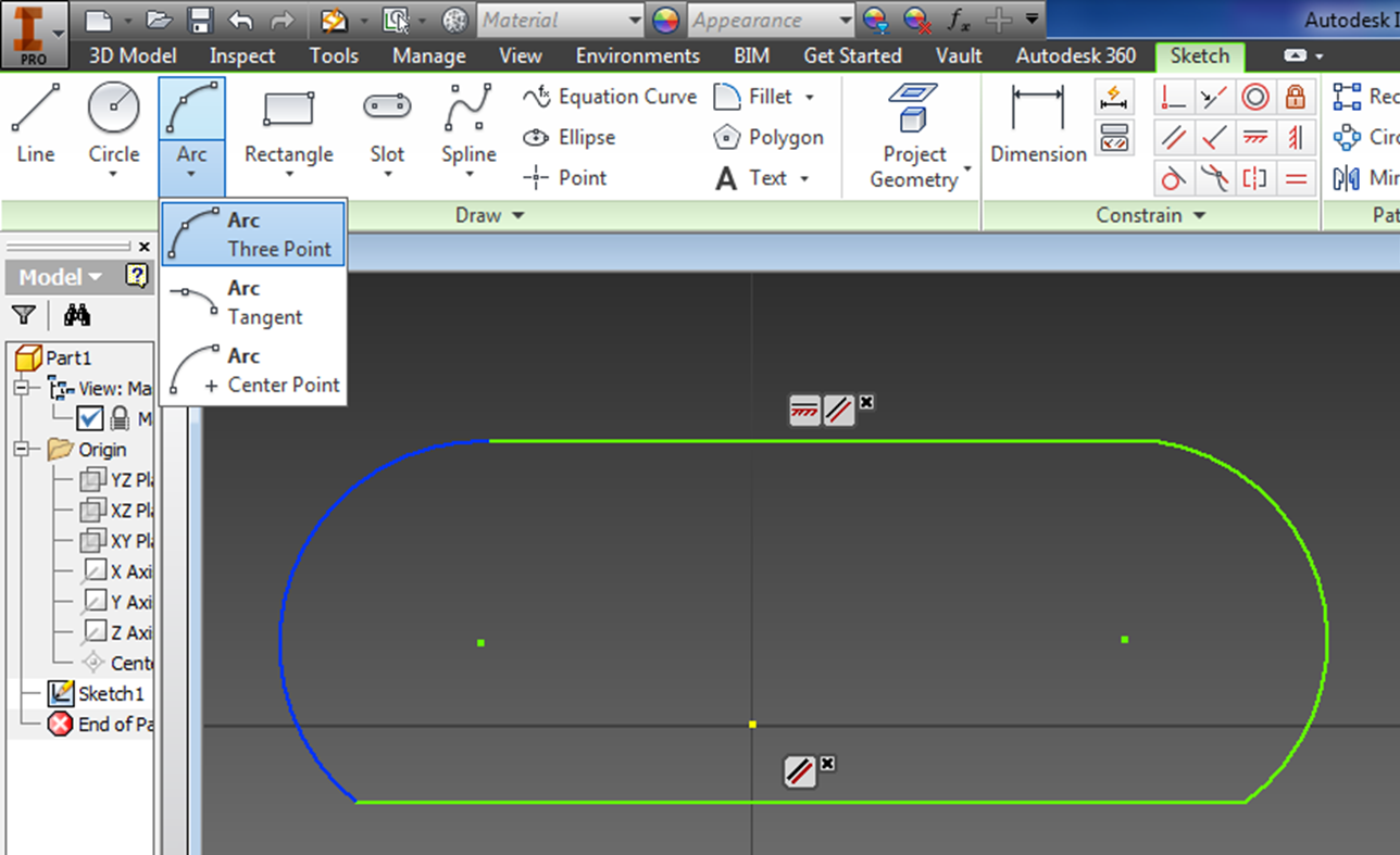
Move your lines around, and see what happens. Move your lines so that the yellow dot is kind of in the center of your drawing.
Let's check out the symmetrical constraint:
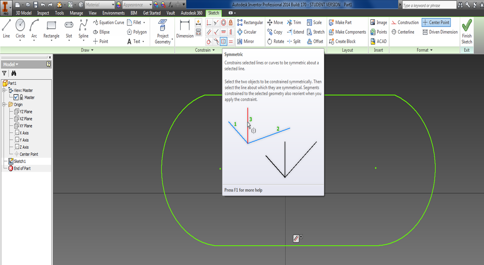
For the symmetrical constraint, we need a line to make them symmetrical around.
Choose "construction line" as this line will not define the part, but is only needed for construction.
Draw a vertical line through the center yellow dot (origin). Notice, that your new line will be automatically constrained (vertical, or perpendicular to the other lines) depending on what points you choose to make it. Inventor makes it very easy to snap and align objects with one another while you are drawing.
If you want to turn auto constrain off, simply hold down the Ctrl key while you are drawing to temporarily disable it.
Construction lines appear dashed and yellow.
Hover your mouse over the symmetrical icon, and follow the directions. "Select the two lines to be constrained symmetrically, then click on the line about which they are to be symmetrical."
Grab a corner, and move your lines around, you will notice that however you move it, all the other lines will move to maintain symmetry about the yellow construction line.
 Now
let's change the length of the lines to create the bottom piece of the
part shown on pg 350 - We will use the dimensioning tool in the
constrain tab:
Now
let's change the length of the lines to create the bottom piece of the
part shown on pg 350 - We will use the dimensioning tool in the
constrain tab:
Hover the mouse over the icon for long enough that the big description comes up. Note that in inventor, dimensioning does not just show how large a part is - it is used to actually change the size of what you are working on.
In inventor, typically you create something, and then dimension it.
(If you dimension while you create it, the dimension is permanently attached to your object, and it is hard to resize it. If you just click randomly, and then go back later and size/dimension it, the dimension is it's own entity that can be deleted etc. which comes in handy when you are trying to trim it later on.)
Click Dimension, then just click on a line (you don't need to click on the end points, just click the line) then pull out the dimension from the line.

Edit the dimension of both of your lines to be 2.3800 (this is the length of the part on pg 350). Note: You might have to use the scroll button on your mouse to recenter your part. (It might get too big, and disappear off your screen.)

Notes:
- The same dimensioning tool works for everything - you don't need to remember "Dimlin" or "dimrad", it will automatically give you a radius if the line you click on is a curve etc.If it gives you the wrong dim, just click on the line again and it will scroll through your options if there are multiple options.
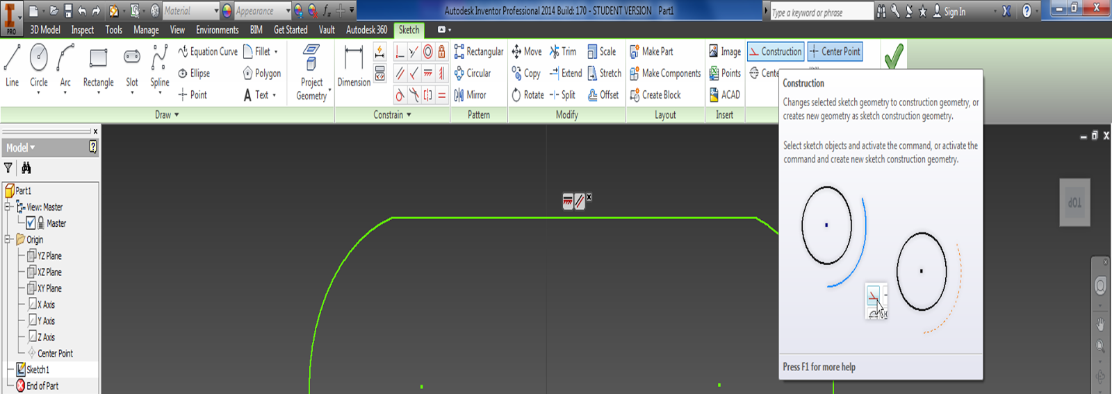
Next, choose:- Construction line
- Rectangle - from center point
- Create a reference rectangle that is 2.38 by 1.875 centered on the yellow dot as shown.
Draw a circle with radius 0.3125, or Diameter .625 in no particular position (we will move it into place using constraints)

Use "Coincident Constraint" to move all of your lines onto your construction rectangle.
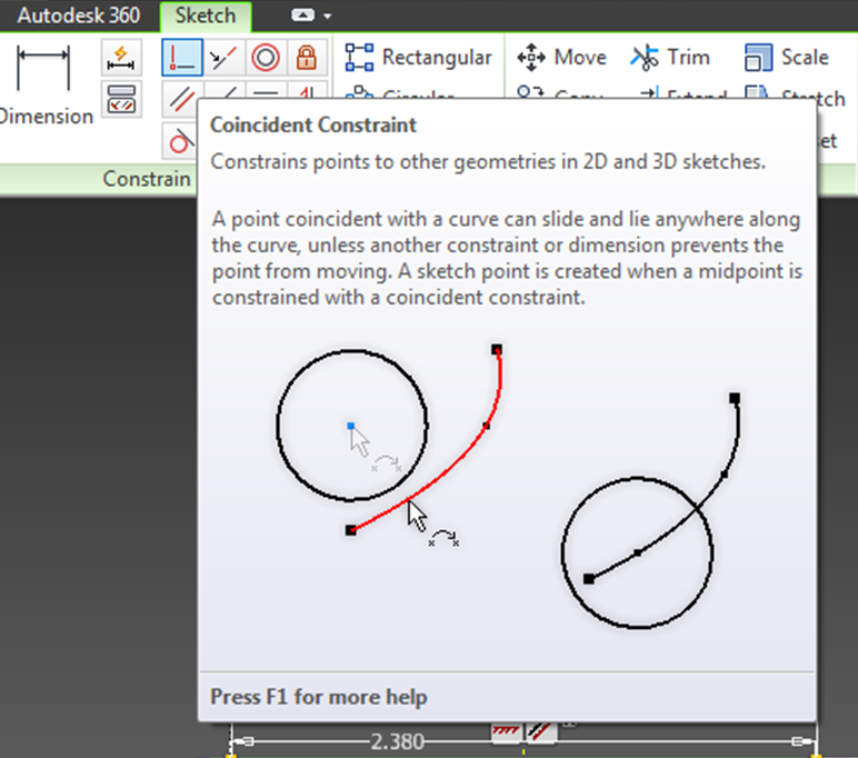
Use "Coincident Constraint" to move your circle onto your construction rectangle:

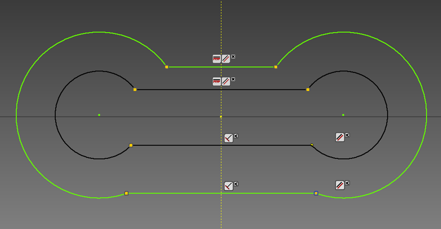
Use tangent to move your circle up to the top line:


Use Mirror to create another circle on the other side of your axis, and delete the previous arcs that were on the ends of your drawing

Create a circle centered on your rectangle center with a radius of 1.65625 or diameter of 3.3125.

Use the Trim command to remove unneeded portions of circles.
Note:
Just click on the line segments you want to get rid of, no need to define a cutting plane in Inventor.
You might have to remove dimensions or constraints to trim some objects.


If you want to fully constrain your finished sketch, you can use the "Fix" locket. Fully constrained lines appear dark purple (you can no longer move them around)


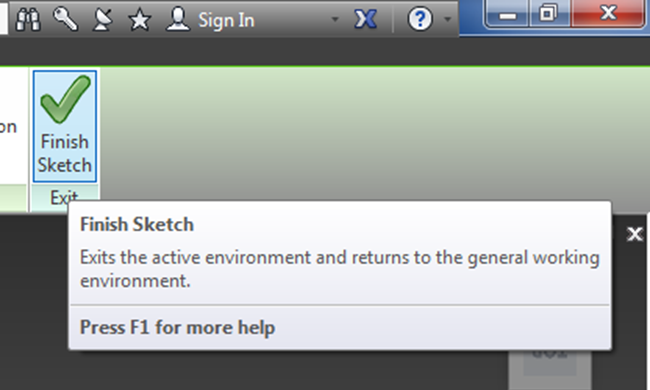
Once everything is correct, select "Finish Sketch" to exit Sketch, and get you back into a 3D environment.
In the 3D Model tab, extrude your base up 0.125in.
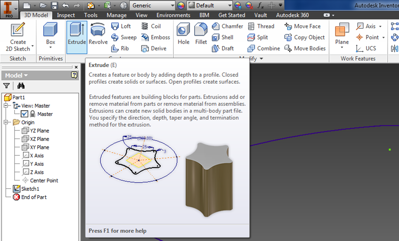
Notice the options in your extrude command:
- Output - solid or surface? pick solid
- Direction - yellow boxes with arrow sticking out, up, down, or symmetrically about the sketch plane.
Can't extrude? Check your Sketch, are all the lines continuous? or are they overlapping one another?

Save your first part as 350base.ipt
Click around in the box on the left hand side - your original sketch is over there, as well as your extrusion.
Instead of layers, you have different files for sketches and 3D parts:

You can click on your sketch and extrusion names to rename them.
Layer #2:
Start a new Sketch from the 3D tab, and use the top face of your base as your sketching plane. Notice the new file you create in the left hand window.

Erase all the yellow lines except for one corner/dot to make the first circle from, then erase the last yellow line. If you don't erase them, they will complicate extruding later on.


Note: You could have gone back later, and created a hole instead of drawing circles into your sketch - look in the 3D ribbon for the hole command.
Also note in your left hand box, you have new files for the new extrusion and sketch.
See if you can finish creating the rest of the base on page 350.

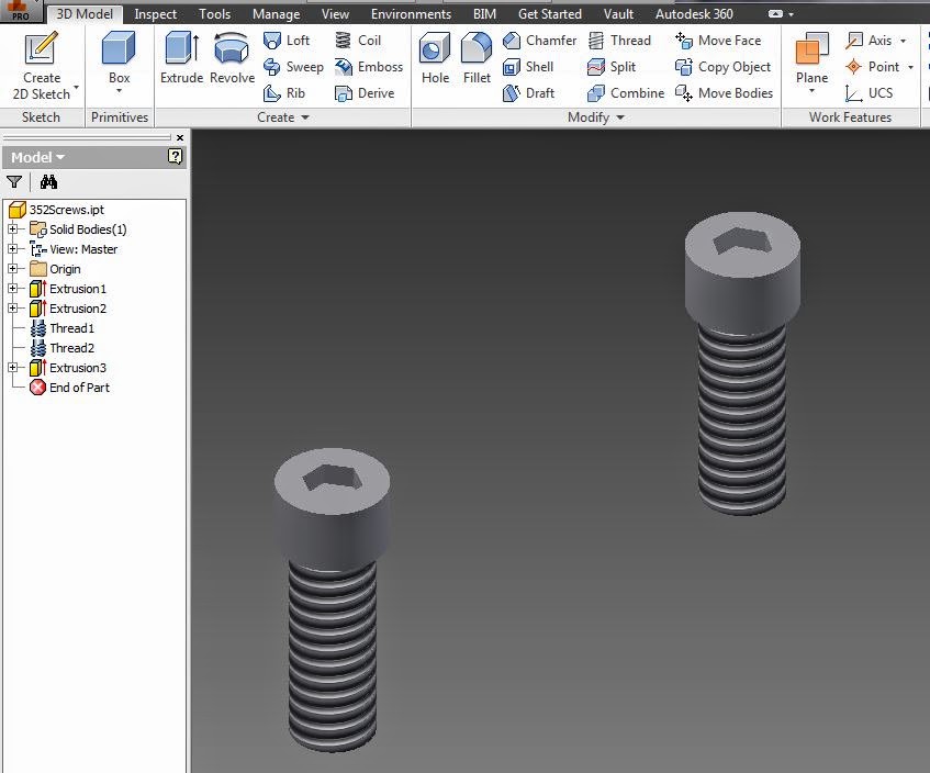
Create a new part for the gasket, and another new part for the screws.

Check out how easily you can add threads to a screw!
Modify →Thread
When you are done creating all of your parts, you can assemble them together.
Choose I - New - and then instead of a part, select assembly.
Click on "Place", then open up your base, gasket, and screws.

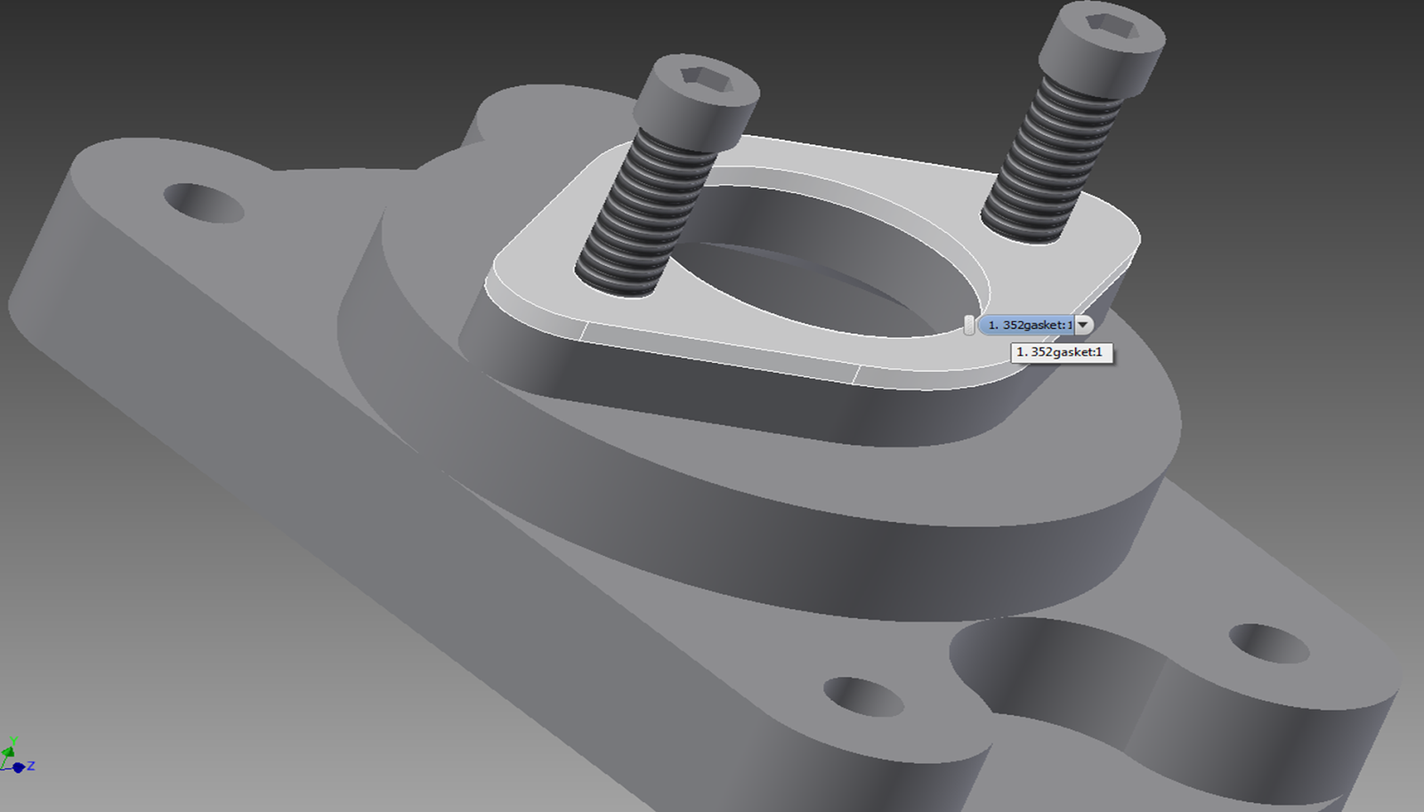
You can move all of your components into place using constraints:

Check out Inventor youtube tutorials if you need them!
Just google what you need:
Constraints: https://www.youtube.com/watch?v=JM-8z3F_464
etc.
No comments:
Post a Comment